
Owner`s manual

6
INSTALLATION
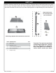
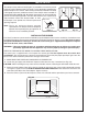
The damper clamp with hex bolt (Fig. 6-1) is provided as a means to prevent
full closure of the damper blade. The clamp is easily attached to most damper
blades with pliers or a wrench, and must be permanently installed. The clamp
is designed to prevent accidental closure of the damper when installed as
illustrated (
Fig. 6-2 and Fig. 6-3). Should the clamp not fi t, or fail to provide the
permanent vent opening listed in the table found above, have a permanent
stop installed, remove the damper blade, or have
the damper cut to provide the minimum permanent
opening required.
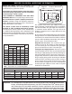
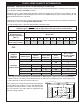
Note: These are minimum damper opening
specifi cations. The damper must be completely
opened when operating this gas appliance to
achieve the best ventilation possible.
Fig. 6-1
Damper clamp
Set screw
Fig. 6-2 Fig. 6-3
Open
Closed
Fig. 6-4
Gas supply
line stub
Gas line
cap
INSTALLING THE BURNER
The Real-Fyre burner system must be installed by a qualifi ed professional service technician. Instructions must
be followed carefully to ensure proper performance and full benefi t from the burner system. This burer system is
designed and labeled for natural gas. Check to be sure natural gas is supplied to the fi replace. Fireplace
fl oor must be level, clean, and smooth.
WARNING: Failure to position the parts in accordance with these diagrams or failure to use only parts
specifi cally approved with this appliance may result in property damage or personal injury.
REFER TO THE PARTS LIST WHEN FOLLOWING THESE INSTRUCTIONS.
The burner pan is supplied with a fuel injector for natural gas. The fuel injector must be used in ALL
installations. The fuel injector has a precisely sized orifi ce to ensure only the proper quantity of gas enters the
burner. This allows maximum performance and gas conservation.
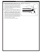
1. MAKE SURE THE FIREPLACE GAS SUPPLY IS TURNED OFF.
2. Locate the gas-supply stub inside the fi replace and remove the cap, if attached (see Fig. 6-4).
CAUTION: When removing the cap, make sure the stub does not turn, loosening the connection inside the wall.
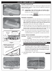
3. Attach the small adapter (Item 3C) to the fuel injector on the burner pan, using a pipe compound resistant
to all gases. Tighten securely. DO NOT REMOVE THE FUEL INJECTOR. Then attach one end of the fl ex
connector (Item 3B) to the small adapter. Tighten securely.
4. Place the burner system into the fi replace so that it is centered and the open burner pan faces outward.