
Owner`s manual

8
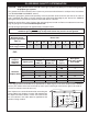
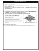
GLASS / GEMS PLACEMENT
Separator
screen
Fig. 8-2
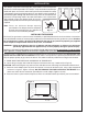
Fig. 8-5
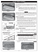
Fig. 8-6
Burner pan
Fig. 8-1
Granules up to
burner tube
(Pack granules in pan
and around tubes)
(If front of screen rises up and does not
rest fl at; bend it downward as needed)
Fig. 8-3
Separator
screen
Burner tubes
Burner pan
Granules level
Granules
sloped
Side view
BURNER PREPARATION
After hooking up the burner to the fi replace gas supply and placing the
heat shield on the valve assembly (if applicable), the decorative media
(granules and glass / gems) must be added for the burner to function
as designed.
Note: Installation is the same for glass and gems. Glass
shown here. These instructions show sand granules being
used as a base for the glass, but only natural-gas burners
use sand. For propane burners, follow these instructions
using vermiculite.
WARNING
The burner and pilot (if equipped) must be OFF (fully extinguished),
and all valve covers must be in place before pouring media onto the
burner. It may also be necessary to temporarily cover the pilot assembly
(if equipped) to keep media out of it during this procedure.
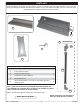
GRANULE PLACEMENT
1. Pour the granules into the pan until they just cover the burner
tubes. Then pack the granules in the pan and around the burner
tubes. Add additional granules as needed to end with the granules
level with the top of the burner tubes. Slope the granules in the
front portion of the pan. See Fig. 8-1 and Fig. 8-3.
2. Place the separator screen over the granules such that the rear
of the screen hooks over the top and back of the burner pan, as
shown in Fig. 8-2 and Fig. 8-3. If the front of the screen rises
up from the fl oor of the pan, bend it downward as needed.
Note: The screen must correctly rest onto the burner pan. If it sits
too high; remove some of the granules to ensure a proper
fi t. DO NOT allow for any granules to be above the screen.
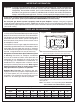
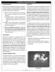
GLASS / GEMS PLACEMENT
CAUTION: Glass pieces may have sharp edges. Be careful handling
the glass. Use hand protection, such as gloves, if
necessary.
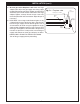
1. Pour the glass / gems directly on top of the granules and screen
so that the burner pan is covered completely and evenly. Relative
to the slope of the burner; DO NOT exceed a 1" depth of glass
(directly above the burner pan) as shown in Fig. 8-4.
Note: At this stage the burner will function as designed; however,
more glass / gems may be added around the burner for
decorative purposes. If glass / gems are desired behind the
burner pan, they may be left at a lower level than the back
of the pan, as shown in Fig. 8-6, or raised up to or above
the level in the back of the pan.
2. Add additional glass / gems around the burner pan as desired
(Fig. 8-6).
Fig. 8-4
Burner pan
1"
Relative to the slope of the
burner; DO NOT exceed a
1" depth of glass (directly
above the burner pan)