
Owner`s manual
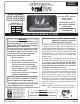
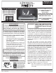

9
Important: When the burner system is installed
outdoors, ensure it is not directly exposed to
the elements (precipitation, rain, wind, etc.).
REFER TO THE BURNER PARTS LIST WHEN FOLLOWING
THESE INSTRUCTIONS.
1. MAKE SURE THE FIREPLACE GAS SUPPLY IS
TURNED OFF.
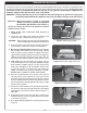
2. Locate the gas-supply stub inside the fi replace and
remove the cap, if attached (reference Fig. 9-1).
CAUTION: When removing the cap, make sure the stub does
not turn, loosening the connection inside the wall.
3. Place the burner system in the fi replace. Center the burner
in the fi replace. (Reference Fig. 9-2 for orientation.)
4. Be sure gas to the fi replace is off. Remove the adapter
that is loosely connected to the fl ex connector (coming
off of the burner system). Attach the adapter to the gas-
supply stub using a pipe compound resistant to all gasses.
Tighten securely. Then attach the open end of the fl ex
connector to the adapter. Tighten securely (See Fig. 9-1).
5. LEAK TEST: Turn on the fi replace gas supply, and test
at all connections for leaks using the appropriate soapy
water solution. If bubbles appear, a leak is present. Turn
off the gas and tighten at all connections. Repeat until
no leaks are present. If a leak persists, turn off the gas
supply and contact the local gas company or dealer.
NEVER USE A FLAME TO CHECK FOR LEAKS.
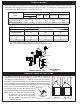
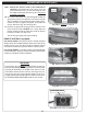
6. Place the (switch/remote receiver) box at the right (or
left) front corner of the fi replace. Be sure to run its wire
through the opening on the right (or left) side of the burner
system, and that the wire remains away from the burner
system and its fl ame during operation (See Fig. 9-2, right
side placement shown).
7. The burner system must be secured to the fi replace fl oor.
The unit has two anchoring tabs located at the bottom
front. With the unit centered, mark and then drill two
1
/
4
"
pilot holes.
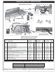
8. Reposition the burner over the pilot holes and insert the
provided hammer screws. Carefully hammer the screws
in as shown in Fig. 9-3.
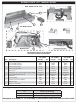
9. Use a power drill to complete the fastening of the screws
(Fig. 9-4).
The Real-Fyre burner system must be installed by a qualifi ed professional service technician. Instructions must
be followed carefully to ensure proper performance and full benefi t from the burner system. Check to be sure
the burner system is designed and labeled for the type of gas (natural or propane gas) supplied to the
fi replace. Fireplace fl oor must be level, clean, and smooth.
WARNING: Failure to position the parts in accordance with these diagrams or failure to use only parts
specifi cally approved with this appliance may result in property damage or personal injury.
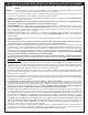
BURNER INSTALLATION
Fig. 9-3 Installing hammer screws
Fig. 9-2 Box location, right or left side
Fig. 9-4 Fastening hammer screws
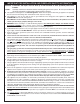
Fig. 9-1 Connect gas supply
Flex connector
Adapter
Gas supply stub