
Owner`s manual

10
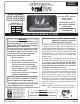
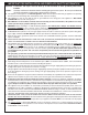
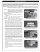
Note: Should the burner need to be removed for
servicing; fi rst unfasten the screw, then use a fl at
head screwdriver to pry up the anchoring tab until
the wedge anchor pops out. See Fig.10-1. The screw
assembly is reusable.
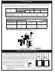
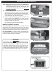
10. The front of the burner has tabs designed to hold the
glass panel in place. First loosen the screws on the tabs
with a screwdriver. Then position the glass panel in place,
secure the tabs up against the panel, and fasten the
screws. Reference Fig. 10-2 and Fig. 10-3.
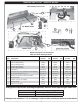
11. Remove the protective coating off of the refl ective rear
panel and front cover . DO NOT use a sharp object to
remove coating. Install the front cover onto the front of
the burner system (see Fig. 10-4).
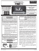
Turn off the gas supply prior to proceeding.
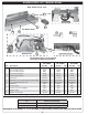
REMOTE SYSTEM (if equipped)
For remote models; the remote system is already installed.
Simply attach the included adapter switch to the front of the
remote receiver (see Fig. 10-5). Read the separate remote
instructions to familiarize yourself with the remote system.
For manual models; if a remote system is purchased later,
read and follow the separate remote instructions (packed with
remote) for complete remote installation.
BURNER INSTALLATION (cont.)
Fig. 10-1 If removal is required
Fig. 10-2 Glass panel positioning
Fig. 10-3 Securing glass panel
Fig. 10-4 Front cover installed
IMPORTANT
For all valves, the air MUST be purged from the gas line
before the pilot will light and burn properly. The time needed
to purge will depend on the length of the gas line to the
unit and the amount of time since the unit or gas line was
last used. It may take several minutes before all the air is
purged and the pilot will light and burn properly. Reference
the LIGHTING INSTRUCTIONS section in this manual.
Fig. 10-5 Install switch (if applicable)
Install adapter switch
A
(Remove)
B
(pry up)