
Owner`s manual


19
FIREPLACE INSTALLATION (cont.)
Liners, Top Body, & Chimney
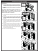
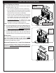
1. Install the fi rebox liners into the interior of the fi rebox in
the order shown in Fig. 19-1.
• The rear liner has grooves to assist in placement.
• Be sure to pull the fl ex connector inside of the fi replace
body through the liner and into the open interior of the
fi rebox (for later R.H.P. burner installation).
• Ensure the unit's marking label plate is placed away
into the upper section of the unit during installation.
It is located in the interior of the fi rebox, and hangs
from a chain on the front inner wall (valve side).
• For Unvented Fireplaces: An additional liner exists
and is to be installed onto the top of the fi rebox
(through the top of the middle body piece).
Note: The liners rest in place. No hardware is required.
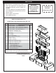
2. Place the top body piece on top of the middle body piece.
Carefully align the pilot holes, and repeat the hardware
installation process using the small hardware kits and two
1
/
2
" open end wrenches (or equivalent). See Fig. 19-2.
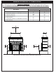
3. Place the chimney piece on top of the top body piece.
Carefully align the pilot holes, and repeat the hardware
installation process (small hardware kits). See Fig. 19-3.
Grout Seams
The seams of the fi replace must be fi nished with a sanded
grout (not included) according to color preference. The
grout can be purchased at a local hardware store. Follow all
instructions provided with the grout.
Recessed Fireplaces Only - Install Finish Substrate
For recessed fi replace models, install the fi nishing substrate as
appropriate. CONSULT A PROFESSIONAL CONTRACTOR
FOR YOUR INDIVIDUAL SETUP.
Fig. 19-1 Install fi rebox liners
Fig. 19-2 Assemble top body
Fig. 19-3 Assemble chimney
A
B
C
C
D
Be sure to pull fl ex
connector through liner
Unvented fi replaces
contain a liner for the
top of the fi rebox.
Hardware:
Small
Bolts x 6
Nuts x 6
Washers x 12
Hardware:
Small
Bolts x 4
Nuts x 4
Washers x 8