
User Manual


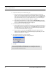

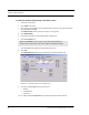

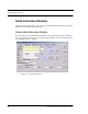
Table Of Contents
- Important Warnings
- Bio-Incompatibility Notice
- Compliance
- Federal Communication Commission (FCC) Compliance
- Industry Canada Compliance
- Overview
- 9450 System
- Quick Response (QR) System
- Integrated Care Management (ICM) System
- Intended Audience
- Additional Detailed Documentation
- Contact Information
- Product Warranty
- Chapter 1
- Introduction
- Central Server and Client Computers
- Computer Specifications
- Quick Look Display
- 9450 System
- Exit Alarm Controller
- Card Reader Access Device
- The Exit Alarm Zone
- Exit Alarm Receiver
- Magnetic Reed Switch
- CodeLock Electromagnetic Lock
- Alarming Band Receivers
- Alarming Band Zone
- Transmitters
- Alarming Band Transmitters
- Mother Transmitter
- Wander Management Transmitter
- CodeWatch Transmitter
- Quick Response System
- Wireless Receiver
- Repeater
- Locator
- Paging Base
- Back-Up Interface
- Pendant Transmitter
- Wall Mount Transmitter
- Pull Cord
- Check-in Pull Cord
- Smoke Detector
- PIR Sensor
- Door/Window Transmitter
- Universal Transmitter
- Code Alert ICM System
- Gateway
- Router
- Quick Look Router
- Transceivers
- Pull Cord
- Check-in Pull Cord
- Wall Mount Emergency Call
- Nurse Call
- Door/Window Transceiver
- Smoke Detector
- PIR Sensor
- Universal Transceiver
- Pendant Transceiver
- Fall Management System
- Fall Management System Control Unit
- Fall Management System Sensor Pad
- Advanced 3-Way Care Solution
- Advanced 3-Way Control Unit
- Advanced 3-Way Care Sensor Pads
- Motion Sensor Pad
- Incontinence Sensor Pad
- Messaging Services
- Event Messaging
- Messaging Delays, Retries and Escalation
- Walkie-Talkie System
- Chapter 2
- Introduction
- Start the Software
- Sleep Mode
- Window Conventions
- Touchscreen Monitor
- Quick Reference Tutorial
- Map Orientation
- Ruleset for Displaying Patient Name
- The Main Window
- The Menu Bar
- Monitor
- Tools
- Messaging
- Asset
- Help
- Top Toolbar
- Bottom Toolbar
- Low Battery Icon
- Chapter 3
- Introduction
- Commonly Used Terms
- Login and Passwords
- Device Supervision
- Inactivity Check-in
- Units
- Global Lockdown
- Common Operations
- Admit
- Admit Information Windows
- Patient Admit Information Window
- Asset Admit Information Window
- Admit Information Tabs
- Patient Main Information Tab
- Asset Main Information Tab
- Medical Information Tab
- Contact Information Tab
- Insert a Picture
- Enter Transmitter Information
- Scheduling an Event
- Discharge
- Escort
- Transfer
- Adjust
- Reports
- Silence
- Chapter 4
- Introduction
- Events
- Devices Displayed on the Map
- Devices Assigned to a Room
- Event Types
- Event Information Window
- Event Information Window Properties
- Red Alarms
- Door Alarm
- Exit Alarm (Wide Gap)
- Smoke Alarm
- Perimeter Alarm
- Cut Band Alarm
- Mismatch Alarm
- Match Alarm
- Link Alarm
- Check Alarm (not “Check Transmitter Alarm”)
- Check Transmitter Alarm
- Assistance Required Alarm
- Fall Alarm
- Wet Alarm
- Turn Alarm
- Server Missing Alarm
- Yellow Alarms
- Check Transmitter Alarm (ICM Pendant)
- Client Missing
- Low Battery
- Device Fault
- White Alarms
- Auto-Enroll
- Admit Complete
- Discharge Expired
- Discharge Complete
- Escort to Expire
- Escort Expired
- Escort Complete
- Transfer to Expire
- Transfer Expired
- Transfer Complete
- Begin Adjust
- Adjust Expired
- Adjust Compete
- Scheduled Event
- Blue Alarms
- Door Alarm
- Cut Band Alarm
- Check Transmitter Alarm
- Light Blue Alarms
- Admit Complete
- Discharge Expired
- Discharge Complete
- Escort to Expire
- Escort Expired
- Escort Complete
- Transfer to Expire
- Transfer Expired
- Transfer Complete
- Adjust Expired
- Adjust Complete
- Scheduled Event
- Chapter 5
- Introduction
- Reports
- Report Buttons
- Sort By Headings
- Additional JCAHO Report Buttons
- System Reports
- Daily Alarms and Activities (Tracer Level 2)
- Alarm Report
- Alarm Activities Report
- Alarm Response Report
- Care Time Report
- Activities Report
- All Activities Report
- All Other Reasons Report
- Facility Trends (Tracer Level 3)
- JCAHO Alarm Trend Report
- JCAHO Assistance Trend Report
- Response Time Trend Report
- Staff Reports (Tracer Level 4)
- Users Report
- User Training Report
- Staff Care Time Report
- Staff Drill Report
- Training Report
- Facility Maintenance (Tracer level 5)
- System Maintenance Report
- Low Batteries Report
- Device Fault Report
- Additional Reports
- Census Report
- Auto Enrolled History Report
- Adjusted Bands Report
- Transfer Report
- Escort Report
- Discharge Report
- Device Hardware Report
- Device Tree Report
- Transmitter Report
- Links Report
- Links Activities Report
- Sensatec Report
- Patient Reports
- Review Info Report
- Review Activity Report
- Review Response Report
- Review Response Reason
- Review Response Reason Detail Report
- Asset Reports
- Asset Transmitter Report
- Asset Activities Report

Chapter 3: Using the Software
48 Series 6.0 Software (0510-1079-B) - User Guide
Inactivity Check-in
An Inactivity Check-in is when the system generates an event when no check-in is received or activity is
detected within the selected period of time. This feature is commonly used with Check-in Pull Cords but can
also be used with a PIR Sensor. If the PIR Sensor does not detect motion within the check-in time period, the
system generates an Assistance Required alarm.
The Inactivity Check-in feature is enabled during the Admit process under the Transmitter tab. Inactivity
Check-in devices must first be assigned to a room/and or unit at the Configuration level (refer to the Series
6.0 Software Administrator Guide).
Units
Upon admission, a patient or asset must be assigned to a Unit. A Unit represents a protected area in your
facility that is monitored as a unit, such as the Nursery or Intensive Care. All devices in the area are assigned
to the unit, and are identified on a map or floor plan specific to the unit.
Some units may have more than one patient or asset occupying the same room. It is important when
admitting a patient or asset to a double-occupancy room that you specify which bed or side of the room the
patient or asset is assigned, for example room 101-A or room 101-B.
If an alarm occurs, the relevant alarm information, such as the patient’s or asset’s name, the type of event, and
the location of the event, is displayed at any Client computer that has been configured to monitor the unit.
Some System Properties, such as the time allowed for the discharge and adjust function, are defined at the
unit level.
Global Lockdown
A Global Lockdown is when all of the doors are automatically locked during a Cut Band alarm. If a door is
already open at the time a Cut Band alarm occurs or if a door is opened at any time while the system is in
Global Lockdown:
• an alarm sounds at the Exit Alarm Controller
• a message is displayed on the Client computer(s) in the unit configured to monitor the
door and on all Quick Look Displays for that unit
• the location of the Exit Alarm is indicated by a flashing icon on the map on the Client
computer(s)
If your facility has enabled the Lockdown on Cut Band Alarms feature, a Cut Band Alarm triggers a Global
Lockdown. You can configure the Global Lockdown feature to lock doors at All exits or By transmitter units.
However if a Cut Band alarm is triggered during an Escort or a Transfer, the system automatically locks All
exits and posts the alarms on all Client computer(s). This is because the transmitter in Escort or Transfer may
be outside of its protected unit.
NOTE: When a transmitter is configured as a low priority asset transmitter, a Cut Band
Alarm will not trigger a Global Lockdown. High Priority configured asset transmitters
will trigger a Global Lockdown.