
User Manual

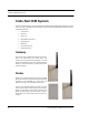

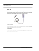
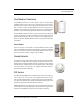
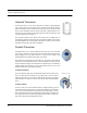
Table Of Contents
- Important Warnings
- Bio-Incompatibility Notice
- Compliance
- Federal Communication Commission (FCC) Compliance
- Industry Canada Compliance
- Overview
- 9450 System
- Quick Response (QR) System
- Integrated Care Management (ICM) System
- Intended Audience
- Additional Detailed Documentation
- Contact Information
- Product Warranty
- Chapter 1
- Introduction
- Central Server and Client Computers
- Computer Specifications
- Quick Look Display
- 9450 System
- Exit Alarm Controller
- Card Reader Access Device
- The Exit Alarm Zone
- Exit Alarm Receiver
- Magnetic Reed Switch
- CodeLock Electromagnetic Lock
- Alarming Band Receivers
- Alarming Band Zone
- Transmitters
- Alarming Band Transmitters
- Mother Transmitter
- Wander Management Transmitter
- CodeWatch Transmitter
- Quick Response System
- Wireless Receiver
- Repeater
- Locator
- Paging Base
- Back-Up Interface
- Pendant Transmitter
- Wall Mount Transmitter
- Pull Cord
- Check-in Pull Cord
- Smoke Detector
- PIR Sensor
- Door/Window Transmitter
- Universal Transmitter
- Code Alert ICM System
- Gateway
- Router
- Quick Look Router
- Transceivers
- Pull Cord
- Check-in Pull Cord
- Wall Mount Emergency Call
- Nurse Call
- Door/Window Transceiver
- Smoke Detector
- PIR Sensor
- Universal Transceiver
- Pendant Transceiver
- Fall Management System
- Fall Management System Control Unit
- Fall Management System Sensor Pad
- Advanced 3-Way Care Solution
- Advanced 3-Way Control Unit
- Advanced 3-Way Care Sensor Pads
- Motion Sensor Pad
- Incontinence Sensor Pad
- Messaging Services
- Event Messaging
- Messaging Delays, Retries and Escalation
- Walkie-Talkie System
- Chapter 2
- Introduction
- Start the Software
- Sleep Mode
- Window Conventions
- Touchscreen Monitor
- Quick Reference Tutorial
- Map Orientation
- Ruleset for Displaying Patient Name
- The Main Window
- The Menu Bar
- Monitor
- Tools
- Messaging
- Asset
- Help
- Top Toolbar
- Bottom Toolbar
- Low Battery Icon
- Chapter 3
- Introduction
- Commonly Used Terms
- Login and Passwords
- Device Supervision
- Inactivity Check-in
- Units
- Global Lockdown
- Common Operations
- Admit
- Admit Information Windows
- Patient Admit Information Window
- Asset Admit Information Window
- Admit Information Tabs
- Patient Main Information Tab
- Asset Main Information Tab
- Medical Information Tab
- Contact Information Tab
- Insert a Picture
- Enter Transmitter Information
- Scheduling an Event
- Discharge
- Escort
- Transfer
- Adjust
- Reports
- Silence
- Chapter 4
- Introduction
- Events
- Devices Displayed on the Map
- Devices Assigned to a Room
- Event Types
- Event Information Window
- Event Information Window Properties
- Red Alarms
- Door Alarm
- Exit Alarm (Wide Gap)
- Smoke Alarm
- Perimeter Alarm
- Cut Band Alarm
- Mismatch Alarm
- Match Alarm
- Link Alarm
- Check Alarm (not “Check Transmitter Alarm”)
- Check Transmitter Alarm
- Assistance Required Alarm
- Fall Alarm
- Wet Alarm
- Turn Alarm
- Server Missing Alarm
- Yellow Alarms
- Check Transmitter Alarm (ICM Pendant)
- Client Missing
- Low Battery
- Device Fault
- White Alarms
- Auto-Enroll
- Admit Complete
- Discharge Expired
- Discharge Complete
- Escort to Expire
- Escort Expired
- Escort Complete
- Transfer to Expire
- Transfer Expired
- Transfer Complete
- Begin Adjust
- Adjust Expired
- Adjust Compete
- Scheduled Event
- Blue Alarms
- Door Alarm
- Cut Band Alarm
- Check Transmitter Alarm
- Light Blue Alarms
- Admit Complete
- Discharge Expired
- Discharge Complete
- Escort to Expire
- Escort Expired
- Escort Complete
- Transfer to Expire
- Transfer Expired
- Transfer Complete
- Adjust Expired
- Adjust Complete
- Scheduled Event
- Chapter 5
- Introduction
- Reports
- Report Buttons
- Sort By Headings
- Additional JCAHO Report Buttons
- System Reports
- Daily Alarms and Activities (Tracer Level 2)
- Alarm Report
- Alarm Activities Report
- Alarm Response Report
- Care Time Report
- Activities Report
- All Activities Report
- All Other Reasons Report
- Facility Trends (Tracer Level 3)
- JCAHO Alarm Trend Report
- JCAHO Assistance Trend Report
- Response Time Trend Report
- Staff Reports (Tracer Level 4)
- Users Report
- User Training Report
- Staff Care Time Report
- Staff Drill Report
- Training Report
- Facility Maintenance (Tracer level 5)
- System Maintenance Report
- Low Batteries Report
- Device Fault Report
- Additional Reports
- Census Report
- Auto Enrolled History Report
- Adjusted Bands Report
- Transfer Report
- Escort Report
- Discharge Report
- Device Hardware Report
- Device Tree Report
- Transmitter Report
- Links Report
- Links Activities Report
- Sensatec Report
- Patient Reports
- Review Info Report
- Review Activity Report
- Review Response Report
- Review Response Reason
- Review Response Reason Detail Report
- Asset Reports
- Asset Transmitter Report
- Asset Activities Report

Chapter 1: Equipment Overview
24 Series 6.0 Software (0510-1079-A) - User Guide
Universal Transceiver
A Universal transceiver can be used to integrate your facility’s existing equipment
such as backup generators, pull-cord devices, or smoke detectors with the software.
Universal transceivers come as either NO (normally open) or NC (normally closed)
devices. They automatically activate when the input from a monitored device has a
contact close or open respectively. When this happens, the Universal transceiver sends
event information to the Central Server.
The Universal transmitter can be placed in the enclosure of an existing device or
inconspicuously mounted near the device. Be sure that the transmitter is not encased in
metal that might block the wireless signal to the Repeater or Receiver. The Universal
transmitter is powered by a replaceable 3-volt battery.
Pendant Transceiver
A Pendant transceiver is a wireless, mobile transceiver that can be worn around the
neck or wrist, or attached to a belt. The protective boot protects the Pendant transceiver
against dropping and water ingress. However to prevent water damage, avoid
prolonged submersion and direct contact with a water stream.
The Pendant can be supervised; if no information is received by the system from the
Gateway for a specified number of times, a Check Transmitter alarm is generated in
the Event List at the computer. Since the Pendant is a mobile device, no installation is
required. Simply insert the battery and set up the Pendant transceiver for use. The
Pendant is powered by a replaceable 3-volt battery.
To Call for Assistance
To call for assistance, firmly press and hold the blue button on the transceiver (for
about a second). Release the button, the green light flashes a series of times to
indicate the transceiver is in an alarm state. If the transceiver flashes red, the signal
is blocked. Move to another area of the room until the signal transmits (flashes
green).
To Clear an Alarm
To clear an alarm or to reset the Pendant transceiver, rapidly but firmly press and
release the blue button on the transceiver six (6) times within three (3) seconds (be
sure to see the green light flash for each push). The green light flashes a series of
times to indicate the transceiver has changed states and is now idle and ready for its
next usage. If the transceiver flashes red, the signal is blocked. Move to another area
of the room until the signal transmits (flashes green).
1-35
1-36
Flashing green light