
User Manual
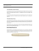
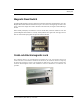
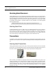
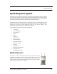
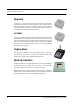
Table Of Contents
- Important Warnings
- Bio-Incompatibility Notice
- Compliance
- Federal Communication Commission (FCC) Compliance
- Industry Canada Compliance
- Overview
- 9450 System
- Quick Response (QR) System
- Integrated Care Management (ICM) System
- Intended Audience
- Additional Detailed Documentation
- Contact Information
- Product Warranty
- Chapter 1
- Introduction
- Central Server and Client Computers
- Computer Specifications
- Quick Look Display
- 9450 System
- Exit Alarm Controller
- Card Reader Access Device
- The Exit Alarm Zone
- Exit Alarm Receiver
- Magnetic Reed Switch
- CodeLock Electromagnetic Lock
- Alarming Band Receivers
- Alarming Band Zone
- Transmitters
- Alarming Band Transmitters
- Mother Transmitter
- Wander Management Transmitter
- CodeWatch Transmitter
- Quick Response System
- Wireless Receiver
- Repeater
- Locator
- Paging Base
- Back-Up Interface
- Pendant Transmitter
- Wall Mount Transmitter
- Pull Cord
- Check-in Pull Cord
- Smoke Detector
- PIR Sensor
- Door/Window Transmitter
- Universal Transmitter
- Code Alert ICM System
- Gateway
- Router
- Quick Look Router
- Transceivers
- Pull Cord
- Check-in Pull Cord
- Wall Mount Emergency Call
- Nurse Call
- Door/Window Transceiver
- Smoke Detector
- PIR Sensor
- Universal Transceiver
- Pendant Transceiver
- Fall Management System
- Fall Management System Control Unit
- Fall Management System Sensor Pad
- Advanced 3-Way Care Solution
- Advanced 3-Way Control Unit
- Advanced 3-Way Care Sensor Pads
- Motion Sensor Pad
- Incontinence Sensor Pad
- Messaging Services
- Event Messaging
- Messaging Delays, Retries and Escalation
- Walkie-Talkie System
- Chapter 2
- Introduction
- Start the Software
- Sleep Mode
- Window Conventions
- Touchscreen Monitor
- Quick Reference Tutorial
- Map Orientation
- Ruleset for Displaying Patient Name
- The Main Window
- The Menu Bar
- Monitor
- Tools
- Messaging
- Asset
- Help
- Top Toolbar
- Bottom Toolbar
- Low Battery Icon
- Chapter 3
- Introduction
- Commonly Used Terms
- Login and Passwords
- Device Supervision
- Inactivity Check-in
- Units
- Global Lockdown
- Common Operations
- Admit
- Admit Information Windows
- Patient Admit Information Window
- Asset Admit Information Window
- Admit Information Tabs
- Patient Main Information Tab
- Asset Main Information Tab
- Medical Information Tab
- Contact Information Tab
- Insert a Picture
- Enter Transmitter Information
- Scheduling an Event
- Discharge
- Escort
- Transfer
- Adjust
- Reports
- Silence
- Chapter 4
- Introduction
- Events
- Devices Displayed on the Map
- Devices Assigned to a Room
- Event Types
- Event Information Window
- Event Information Window Properties
- Red Alarms
- Door Alarm
- Exit Alarm (Wide Gap)
- Smoke Alarm
- Perimeter Alarm
- Cut Band Alarm
- Mismatch Alarm
- Match Alarm
- Link Alarm
- Check Alarm (not “Check Transmitter Alarm”)
- Check Transmitter Alarm
- Assistance Required Alarm
- Fall Alarm
- Wet Alarm
- Turn Alarm
- Server Missing Alarm
- Yellow Alarms
- Check Transmitter Alarm (ICM Pendant)
- Client Missing
- Low Battery
- Device Fault
- White Alarms
- Auto-Enroll
- Admit Complete
- Discharge Expired
- Discharge Complete
- Escort to Expire
- Escort Expired
- Escort Complete
- Transfer to Expire
- Transfer Expired
- Transfer Complete
- Begin Adjust
- Adjust Expired
- Adjust Compete
- Scheduled Event
- Blue Alarms
- Door Alarm
- Cut Band Alarm
- Check Transmitter Alarm
- Light Blue Alarms
- Admit Complete
- Discharge Expired
- Discharge Complete
- Escort to Expire
- Escort Expired
- Escort Complete
- Transfer to Expire
- Transfer Expired
- Transfer Complete
- Adjust Expired
- Adjust Complete
- Scheduled Event
- Chapter 5
- Introduction
- Reports
- Report Buttons
- Sort By Headings
- Additional JCAHO Report Buttons
- System Reports
- Daily Alarms and Activities (Tracer Level 2)
- Alarm Report
- Alarm Activities Report
- Alarm Response Report
- Care Time Report
- Activities Report
- All Activities Report
- All Other Reasons Report
- Facility Trends (Tracer Level 3)
- JCAHO Alarm Trend Report
- JCAHO Assistance Trend Report
- Response Time Trend Report
- Staff Reports (Tracer Level 4)
- Users Report
- User Training Report
- Staff Care Time Report
- Staff Drill Report
- Training Report
- Facility Maintenance (Tracer level 5)
- System Maintenance Report
- Low Batteries Report
- Device Fault Report
- Additional Reports
- Census Report
- Auto Enrolled History Report
- Adjusted Bands Report
- Transfer Report
- Escort Report
- Discharge Report
- Device Hardware Report
- Device Tree Report
- Transmitter Report
- Links Report
- Links Activities Report
- Sensatec Report
- Patient Reports
- Review Info Report
- Review Activity Report
- Review Response Report
- Review Response Reason
- Review Response Reason Detail Report
- Asset Reports
- Asset Transmitter Report
- Asset Activities Report

Chapter 1: Equipment Overview
10 Series 6.0 Software (0510-1079-A) - User Guide
Alarming Band Receivers
Alarming Band Receivers are placed strategically throughout the monitoring area to receive signals from the
alarming band transmitters worn by patients. When the Cut Band feature is enabled, the system provides an
alert if the banding material that holds the transmitter to the patient is tampered with, cut, or opened without
authorization. Multiple receivers are used to ensure reception of the signal if there is an effort made to shield
the transmitter during abduction or elopement attempts. For more information, see the Alarming Band
Receiver Installation Guide.
Alarming Band Zone
An Alarming Band Zone is the area within range of an Alarming Band Receiver, several of which are
mounted above the ceiling tiles of a facility. If a Cut Band alarm is triggered in an Alarming Band Zone, an
alarm is sounded on all Client computers assigned to monitor the transmitter’s unit, a message is displayed in
the Event List, and the location of the Alarming Band Receiver that detected the event is indicated on the map
on the Client computer(s). Cut Band alarms are also posted on remote notification devices.
Transmitters
A transmitter is a device that periodically transmits a signal containing data to uniquely identify it from other
transmitters. Some transmitters are also capable of transmitting information to identify that the band has been
cut.
Alarming Band Transmitters
Alarming band transmitters are placed on the ankle or wrist of a patient or affixed to an asset. The transmitter
becomes active once the banding material remains connected on both sides with banding material in place for
60 seconds. The 60-second window exists to allow for proper adjustment of the banding material.
After one minute, the transmitter ID is displayed in the Event List and information of the patient or asset
wearing the transmitter can be associated with the transmitter using the Admit or Auto-Enroll function.
Alarming band transmitters can be supervised. If a transmitter is configured for Supervision, and fails to
regularly communicate to the system, a Check Transmitter alarm will result in the Event List at the computer.
For more information about securing, cleaning, and troubleshooting transmitters, see the appropriate
Transmitter User Guide.
NOTE: The Mother/Infant function requires applicable Alarming Band Receivers.
Infant Transmitter
Patient Transmitter
1-08
1-09