
User's Manual

CHAPTER 1 Installing Hardware Components
Quick Response Premiere Wireless Call System Hardware Installation Guide Page 27 of 64
0510-1099-E
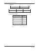
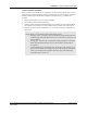
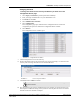
LED Sequence
Below is an explanation of the LED sequence.
LED Power Up Sequence
Explanation of LED
L1, L2, L3, L4 (sequentially)
Device executing normal firmware.
All LEDs On (not maintained)
Device executing normal firmware.
NOTE: If power up sequence does not occur and the green light is blinking every second, than the device is in
manufacturer’s mode.
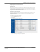
LED Display Sequence
Explanation of LED
Dual Green LED Flash (10 times)
Device is attempting to identify a Router/Gateway parent.
Single Green LED Flash (L2)
Successfully joined with and checked in with identified parent.
Single Red LED Flash (L1)
No response from identified parent.
Repeating (dim) Red LED Flash (L3)
Device operating normally, flashes once per second (heart beat indicator).
Dual Green LED Flash (one time)
Router/Gateway Successfully forwarded packet from a child to the
Central Server or display.
Single Green LED Flash (L4)
Gateway received the check in message sent by Server every 15 seconds.
L3 and L4 Solid Illumination
Battery switch turned off or battery fully discharged and requiring the
Quick Response Premiere Router Battery Recharger procedure
(PN 0510-0336).
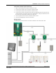
Gateway/Router Channel Default
The Gateway and Router default to channel 25. In a facility with a single Gateway, it is
recommended to leave the Gateway and Routers on channel 25. In a facility with multiple
Gateways, it is recommended to power-up only one Gateway system at a time during
installation. Once the first Gateway/Router system is up and running, switch that system to
another channel, then commission the next Gateway system (refer to “Additional
Gateway/Router Installation” on page 26).