
User's Manual


CHAPTER 1 Installing Hardware Components
Page 20 of 64 Quick Response Premiere Wireless Call System Hardware Installation Guide
0510-1099-E
Wiring Dome Lights
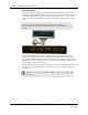
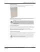
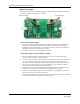
The illustration below shows the option jumpers for the Dome Light used with the 32 Channel
Controller. Verify that all 4 jumpers are set to NC.
White Circuit (NC) Red Circuit (NC)
To wire power to Dome Lights
1. Run wiring conduit from Dome Light to Dome Light and terminate at the Central Power
Supply. The current requirement for the Dome Light is 50mA. Each circuit should be
limited to 8 or fewer Dome Lights. Use 16 AWG 2-conductor cable to connect the Dome
Light power terminals to the Central Power Supply.
2. Terminate the wires per the Wiring Diagram on page 21.
To wire Dome Lights to the 32 Channel Controller
1. Run a 22 AWG 4-conductor or 8-conductor cable to connect one of the Dome Light
circuit’s terminals to the 32 Channel Controller.
2. Connect one pair of the cable conductors from the Dome Light’s C1(+) and C2 terminals to
one of the 32 Channel Controller’s relay output circuits. The 32 Channel Controller’s
circuits 01 and 02 have both Normally Open (NO) and Normally Closed (NC) contacts; if
these circuits are utilized, wire to the C and NO terminals. The 32 Channel Controller’s
circuits 03 thru 32 have Normally Open (NO) contacts.
3. Repeat the above step for the second Dome Light circuit (C3 and C4) using either another
4-conductor cable or the 3rd and 4th pairs of the 8-conductor cable, if used.
4. Use the tie wrap provided to wrap around the terminated wires and tightly attach it to the
holes in the 32 Channel Controller circuit board.
5. Once the Dome Light has been wired, slip the wires back into the wall until the two support
posts on the circuit board rest against the mounting surface.