
User's Manual


CHAPTER 1 Installing Hardware Components
Page 16 of 64 Quick Response Premiere Wireless Call System Hardware Installation Guide
0510-1099-E
To install the Quick Look Router with Quick Look Display
Use the following steps to mount the Quick Look Display.
WARNING: When installing a product, you must follow standard, accepted
safety practices, such as wearing safety glasses.
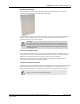
1. Feed the wire attached to the head assembly of the Quick Look Display through the un-
notched end of the 4” wall-mount bracket.
2. Slide the head assembly onto the end of the 4” wall-mount bracket.
3. Secure it in place by tightening the set screw located on the end of the post or bracket.
4. Align the notches in the Quick Look base with the notches in the 4” wall-mount bracket
and hold together.
5. Feed the retaining nut over the wires leading out of the bottom of the base.
6. Tighten the retaining nut.
7. Be careful not to strip or damage the mounting base assembly.
8. Screw the base into the wall using the four screws provided.
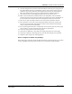
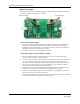
9. Wire the Router for power via the power terminal in the Router, noting the correct polarity.
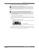
10. Make certain that the Router’s ON/OFF switch is in the ON position. After the ON/Off
switch is turned to the ON position, the LED’s at the bottom of the device should flicker. If
they do not flicker then turn the switch to the OFF position and then turn it back ON.
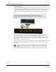
11. Mount the Router within 4-feet of the Quick Look Display, near a 110 VAC wall outlet.
12. Connect the Router’s power supply to a 110 VAC wall power outlet.
To test the Routers
1. For each Router use a Pendant that is in Survey Mode to test reception. Walk to the far
reaches of adjacent rooms and covered area to ensure that acceptable coverage is achieved.
2. For Quick Look Routers, verify location data and alarm information appears on the display
when an alarm is generated.
3. For more information contact or for technical support, contact the Technical Support Team
at (800) 669-9946 or (262) 790-1771.