
User's Manual


CHAPTER 1 Installing Hardware Components
Quick Response Premiere Wireless Call System Hardware Installation Guide Page 15 of 64
0510-1099-E
To install the Quick Look Router with High Visibility Display
WARNING: When installing a product, you must follow standard, accepted
safety practices, such as wearing safety glasses.
Mount the High Visibility Display in the desired location, near a 110 VAC wall outlet. Use the
following steps for mounting the High Visibility Display as a wall-mount or counter-mount
display.
WARNING: It is crucial that the following steps be carried out in the order
listed. If the display is not powered and connected properly to the Router
when the Router is initially powered on, the display will not function.
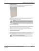
1. Attach mounting brackets 281/8 inches apart, in desired location. If mounting in drywall,
screw anchors must be used.
2. Once brackets are in place, put the display between the two brackets and secure it to the
brackets with the two thumb screws provided.
3. To maximize visibility, first adjust the tilt of the display and then tighten the thumb screws.
4. Plug the 7 VAC 4.8A power supply into the High Visibility Display and connect it to wall
power outlet.
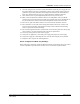
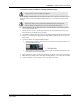
5. Connect the Router to the High Visibility Display.
Plug the RJ-45 end of the 10-foot connector cable into the RJ-45 port on the back of
the High Visibility Display.
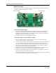
Plug the RS-232 end of the 10-foot connector cable into the RS-232 terminal on the
lower right hand corner of the Router.
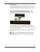
6. Wire the Router for power via the power terminal in the Router, noting the correct polarity.
7. Mount the Router within 10-feet of the High Visibility Display, near a 110 VAC wall outlet.
8. Connect the Router’s power supply to a 110 VAC wall power outlet.