
User's Manual


CHAPTER 1 Installing Hardware Components
Quick Response Premiere Wireless Call System Hardware Installation Guide Page 13 of 64
0510-1099-E
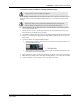
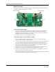
8. Once the wiring has been run to the location of the Router attach the power supply wires to
the terminal block in the corner of the Router. If using a central power supply up to seven
(7) Routers may be daisy chained by terminating the next Router to the second terminal
block. The minimum field wire size to be employed shall be 18 AWG (0.36 mm2).
9. Insure that the wires are pulled tight through the wire tie wrap and cut excess.
10. Make certain that the Router's ON/Off switch is in the ON position. After the ON/Off
switch is turned to the ON position, the LED’s at the bottom of the device should flicker. If
they do not flicker then turn the switch to the OFF position and then turn it back ON.
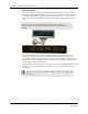
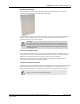
11. Place the rear plate of the Router into the recess on the back of the Router enclosure.
12. Place the Router over the wall anchors in alignment with the holes in the enclosure and
insert two screws (included). Verify Router is firmly secured to the intended mounting
surface to prevent the device from falling.
13. For extended range Routers make certain that the external antenna points over the top edge
of the enclosure. Any other orientation will reduce device performance.
14. If raceway is being used now is the time to apply it.
15. If the power is supplied by a wall outlet power supply, then plug in the power supply.
16. If the power supply has a mounting tab, secure it to the outlet using the screw provided.
17. Repeat the above steps for the remaining Routers.
Router Configuration in Multi-story Buildings
When configuring a multi-story facility the Routers should be placed directly above one another
as much as possible to provide accurate location even in non-location required facilities.