
User's Manual


CHAPTER 1 Installing Hardware Components
Page 12 of 64 Quick Response Premiere Wireless Call System Hardware Installation Guide
0510-1099-E
To take a Pendant out of Survey Mode
1. Remove the 3V Lithium coin cell battery from the Pendant
2. Insert a “new” battery into battery holder of the Pendant. Do NOT hold the button down.
The Pendant is now ready for normal use (refer to “Pendant Transceivers” on page 55).
CAUTION: A Pendant in Survey Node depletes the battery quickly. It is
important to insert a new battery into the Pendant for use after Survey Mode is
completed.
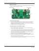
Determine Placement of Routers
NOTE: A configuration map or floor plan of the facility is pre-determined with most Quick
Response Premiere Wireless Call Systems. Please rely on the configuration map or floor plan
in conjunction with the information provided below to determine Router placement.
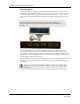
Routers are powered by a plug-in power supply or central power supply. A backup battery is
also included in the Router enclosure. Routers can be placed on either the wall or on the ceiling.
If mounting to the ceiling, the issue of bleeding through to the floor above must be considered.
Other factors that affect the placement of Routers are the availability of a power source and
sufficient coverage for the supervision of transceivers.
1. The first Router's location is in the proximity of the Gateway as specified on the floor plan.
Using a Pendant that is in Survey Mode, walk a distance from the Gateway until the light
on the Pendant starts blinking red. This indicates that the Router is out of range of the
Gateway.
2. Walk back into range.
3. Mount Router within range of the Gateway and near a 110 VAC wall outlet or at the
termination point from the central power supply. Repeat steps 1 and 2 to mount subsequent
Routers.
NOTE: If using a 9V power supply, wiring from the power supply can be routed inside the wall
or (if preferred) mount the raceway for containing and concealing the wires leading from the
underside of the Router down to the 110 VAC wall outlet.
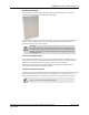
4. For wall placement, the Router should not be located over a stud and should be at a
distance of one foot from the bottom of the enclosure to the ceiling.
5. For ceiling placement, the Router should mounted down the center of the hallway or
centered in a room. Its orientation can be parallel or perpendicular to the walls of the
hallway. For optimal location, mount Router in the center of the ceiling tile.
6. Using the rear plate of the Router as a template, place it level against the intended mounting
surface and mark the location of the two mounting holes. If the wiring from the wall outlet
power supply or central power supply exits from the intended mounting surface then locate
the lower right corner of the rear plate (corner is cut out) over the exit hole.
7. Center punch each hole and drill in two nylon wall anchors (included). If the Router is
located on a concrete mounting surface then you must use the wall anchors designed for
use with concrete (not included). If the Router is to be installed on drop ceiling tiles use the
threaded drywall anchor taking care to not damage ceiling tile during installation process.