
User's Manual

CHAPTER 1 Installing Hardware Components
Page 10 of 64 Quick Response Premiere Wireless Call System Hardware Installation Guide
0510-1099-E
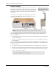
4. Make certain that the RS232/Power Cable is plugged into the Gateway and that the ON/OFF switch
is in the ON position. After the ON/Off switch is turned to the ON position, the LED’s at the bottom
of the device should flicker. If they do not flicker then turn the switch to the OFF position and then
turn it back ON.
5. Depending on which serial port server you use, do one of the following:
a. When using a 4-port serial port server (PN 9450-0910) with cable (PN 0460-0101), connect the
RJ45 connector from the Gateway to the top side of the serial port server. The serial port server
is located within the black box mounting assembly.
b. When using a single serial port server (PN 9600-0002) with cable (PN 0460-0124), connect the
9-Pin connector from the Gateway to the single serial port server. Run Cat-5 wiring using
standard 568B and terminate each end with a RJ45 connector. Connect one end to the
c. Ethernet connector on the bottom of the single serial port server and the other end to the
Ethernet switch.
Then, either plug the serial port into the CPS observing the polarity of the cable, red to (+ ) and black
to ( - ) or plug the power supply into a standard outlet. Using an uninterruptable power supply (UPS)
is recommended for standard output power.
6. Ensure that the wires are pulled through the wire tie wrap, secure them tightly with the wire tie and
cut off excess.
7. Place the rear plate of the Gateway into the recess on the back of the Gateway enclosure.
8. With the antenna pointing upwards, place the Gateway over the wall anchors in alignment with the
holes in the enclosure and insert two screws (included). Verify Gateway is firmly secured to the wall
to prevent device from falling.
9. Using the software loaded on the Central Server select the COM port assigned to the Gateway.
Refer to the section “Poll Server Settings” in the applicable Series Software Administrative Guide.
To test the Gateway
1. From Server Management home page, select Scan Devices.
2. From the Configuration home page, select Devices.
3. Verify the Gateway appears in the device list.
4. Activate a transceiver and initiate an alarm event.
5. The transceiver should now appear in the device list under the same Com Port as the Gateway.
6. If the transceiver does not populate in the device list, verify that the appropriate communications
port is selected and the Gateway is powered.