
User's Manual

CHAPTER 1 Installing Hardware Components
Quick Response Premiere Wireless Call System Hardware Installation Guide Page 9 of 64
0510-1099-E
To install the Gateway directly to Server computer
1. Locate a mounting site for the Gateway that is within a 12-foot reach of the Central Server. To
minimize noise interference, the Gateway should be a minimum of 10-feet away from the paging
base or any high powered electrical device.
Placement of the Gateway should not be located over a stud. The Gateway should be at a one-foot
distance from the bottom of the enclosure to the ceiling.
2. Using the rear plate of the Gateway as a template, place it level against the wall and mark the
location of the two mounting holes.
3. Center punch each hole and insert two nylon wall anchors (included).
4. Make certain that the RS232/Power Cable is plugged into the Gateway and that the ON/Off switch
is in the ON position. After the ON/Off switch is turned to the ON position, the LED’s at the
bottom of the device should flicker. If they do not flicker then turn the switch to the OFF position
and then turn it back ON.
5. Place the rear plate of the Gateway into the recess on the back of the Gateway enclosure.
6. With the antenna pointing upwards, place the Gateway over the wall anchors in alignment with the
holes in the enclosure and insert two screws (included).
7. If preferred, mount the raceway for containing and concealing the wires leading from the underside
of the Gateway down to the Central Server.
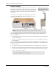
8. Connect the 9-Pin serial connector from the Gateway to the serial port on the Central Server.
9. Plug the power supply into a standard outlet. Using an uninterruptable power supply (UPS) is
recommended.
10. If the power supply has a mounting tab, secure it to the outlet.
11. Using the software loaded on the Central Server, select the COM port assigned to the Gateway.
Refer to the section "Poll Server Settings" in the applicable Series Software Administrator Guide
(PN 0510-1118).
To install the Gateway in or near a wiring closet
1. Locate a mounting site for the Gateway within the wiring closet. Placement of the Gateway should
not be located over a stud. The Gateway should be at a one-foot distance from the bottom of the
enclosure to the ceiling.
NOTE: In some circumstances where RF performance is impaired by a shielded wiring closets
or the location of the covered area is at a significant distance from the wiring closet, the
Gateway can be located outside the wiring closet by making use of the
provided 50 foot RS232/Power Cable.
2. Using the rear plate of the Gateway as a template, place it level against the wall and mark the
location of the two mounting holes.
3. Center punch each hole and insert two nylon wall anchors (included).