
User's Manual

CHAPTER 1 Installing Hardware Components
Page 8 of 64 Quick Response Premiere Wireless Call System Hardware Installation Guide
0510-1099-E
Install the Gateway
The Gateway receives signals from Routers and transceiver devices and
sends them to the Central Server. The Gateway can be supervised; if no
information is received by the system from the Gateway for a specified
amount of time, a Device Fault alarm is generated in the Event List at
the computer.
The Gateway has four (4) single-color LED lights; two green and two
red. For more information on LED lights and LED sequence refer to
“LED Sequence” on page 25.
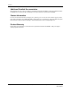
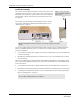
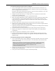
NOTE: Antenna PN 0330-0044
must be used with the installation
of the Gateway.
Antenna
NOTE: The RF lights do not flash on the Router or Gateway in response to end device
activity.
The two set of lights furthest from the Reset Button indicate transceiver device communication status.
These set of lights flashes briefly (once) every check-in (15 seconds by default) and when data is
received or transmitted.
Green indicates communication is good (received data is formatted properly or the transmitted data
was sent successfully).
Red indicates communication failure (received data has an error or the transmitted data was NOT
sent successfully).
The two set of lights closest to the Reset Button indicate RS232 communication status with the Central
Server. These set of flights flashes briefly (once) when data is transmitted via an external RS232 device
to the Central Server.
Green indicates communication is good (transmission data acknowledged by the Central Server).
Red indicates communication failure (transmission data NOT acknowledged by the Central Server).
A repeating, dim red LED flash (flashes once per second) indicates the device operating normally.
Refer to “LED Sequence” on page 25.
NOTE: The Gateway must be mounted as high as possible from the ground and situated
where reception to affiliated Routers is not impaired.