
User Manual
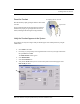
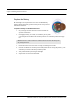


Table Of Contents
- Important Warnings
- Bio-Incompatibility Notice
- Compliance
- Introduction
- About this Guide
- Additional Detailed Documentation
- Contact Information
- Product Warranty
- Chapter 1
- Introduction
- Installation Checklist
- Installing Components
- Install the Central Server
- Install the Gateway
- Install Routers
- Place a Pendant into Survey Mode
- Determine Placement of Routers
- Quick Look Router
- Gateway/Router Reset Button
- LED Sequence
- Gateway/Router Channel Default
- Additional Gateway/Router Installation
- Changing Channels
- Router Depth
- Rebuild Subnet on Scanned Devices
- Scan Devices
- Chapter 2
- Introduction
- Transceiver Devices
- LED Light Indicator
- Installing Transceiver Devices
- Pull Cords/Emergency Call
- Check-in Pull Cord
- Pull Cord Transceiver with Extended Battery Pack
- Wall Mount Emergency Call
- Universal Transceiver
- Tamper
- Nurse Call
- Door/Window Transceiver
- Door/Window Transceiver with Reset Button
- PIR Sensor
- Smoke Detector
- Pendant Transceivers
- Activate the Battery
- Set up the Pendant
- Reset the Pendant
- Verify the Pendant Appears in the System
- Replace the Battery
- Test the System Operation
- Chapter 3
- Introduction
- Device Failure
- Router Failure
- Gateway Failure
- Chapter 4
- Specifications
- Power Cable Run Lengths
- Mesh Network Router/Gateway
- Quick Look Display for Quick Look Router
- Pendant Transceiver
- Pull Cord
- Nurse Call
- Door/Window Transceiver
- PIR Sensor
- Smoke Detector
- Universal Transceiver

Chapter 3: Maintenance
48 9600 Series Wireless Call System (0510-1078-D) - Hardware Installation Guide
11. Reattach the external antenna.
12. Connect the power and serial cable on the replacement Gateway.
13. Note the LED sequence on the RS232 status LED. Refer to the LED Sequence Chart for a Service
Replacement (page 12).
14. Physically mount the replacement Gateway.
15. Looking at the Dashboard, verify that the Gateway is checking in every 15 seconds.
16. From the software application, initiate a Reset.
a. go to the Server Management page
b. select the ComPort that the new Gateway is connected
c. click Reset
17. Ensure that all Device Fault events are resolved.
18. Using a RMA form, return the failed Gateway’s circuit board and the replacement Gateway
enclosure to RFT for analysis.