
User Manual
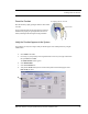
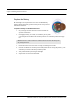


Table Of Contents
- Important Warnings
- Bio-Incompatibility Notice
- Compliance
- Introduction
- About this Guide
- Additional Detailed Documentation
- Contact Information
- Product Warranty
- Chapter 1
- Introduction
- Installation Checklist
- Installing Components
- Install the Central Server
- Install the Gateway
- Install Routers
- Place a Pendant into Survey Mode
- Determine Placement of Routers
- Quick Look Router
- Gateway/Router Reset Button
- LED Sequence
- Gateway/Router Channel Default
- Additional Gateway/Router Installation
- Changing Channels
- Router Depth
- Rebuild Subnet on Scanned Devices
- Scan Devices
- Chapter 2
- Introduction
- Transceiver Devices
- LED Light Indicator
- Installing Transceiver Devices
- Pull Cords/Emergency Call
- Check-in Pull Cord
- Pull Cord Transceiver with Extended Battery Pack
- Wall Mount Emergency Call
- Universal Transceiver
- Tamper
- Nurse Call
- Door/Window Transceiver
- Door/Window Transceiver with Reset Button
- PIR Sensor
- Smoke Detector
- Pendant Transceivers
- Activate the Battery
- Set up the Pendant
- Reset the Pendant
- Verify the Pendant Appears in the System
- Replace the Battery
- Test the System Operation
- Chapter 3
- Introduction
- Device Failure
- Router Failure
- Gateway Failure
- Chapter 4
- Specifications
- Power Cable Run Lengths
- Mesh Network Router/Gateway
- Quick Look Display for Quick Look Router
- Pendant Transceiver
- Pull Cord
- Nurse Call
- Door/Window Transceiver
- PIR Sensor
- Smoke Detector
- Universal Transceiver

9600 Series Wireless Call System (0510-1078-D) - Hardware Installation Guide 47
Gateway Failure
17. Restore each Pull Cord and Universal from step 6.
a. With battery still removed, press the tamper switch a few times (ensures caps are discharged
and device performs a proper power-up reset).
b. Insert battery.
c. Verify device light indicator blinks green 3 times.
d. Re-mount device.
18. Alarm and clear each Pull Cord and Universal and verify the PC reports each alarm and clear.
19. Open the Device Tree Report and verify that none of the Routers, Pull Cords and Universal devices
are reporting an FFFF short address or have a path that states “Parent is not real”. If the Pull Cords
or Universal devices are, remove their battery, press the tamper switch a few times and replace the
battery. If the Routers are, rebuild the network from that point out using the above procedure or
execute the Rebuild functionality to fix.
Gateway Failure
When a Gateway fails, its Personal Area Network ID (PAN ID) remains in the system. Routers and end
devices search for connectivity to a single Gateway’s PAN ID. The PAN ID is based on the Media Access
Control address (MAC address) of the Gateway.
To replace a failed Gateway
1. Unpower and physically remove the failed Gateway.
a. turn off the Gateway
b. remove the serial cable
c. remove the external antenna
d. remove the board from the enclosure
2. Prepare the replacement Gateway.
a. remove the antenna from the replacement Gateway
b. remove the board from the enclosure
c. place the new Gateway in the old enclosure
3. Execute the Gateway Service Set MAC ID Utility.
4. Connect the replacement Gateway to the service technician’s laptop through the serial port or
PortServer.
5. Start the Set MAC ID Utility.
6. Enter the comport of the Gateway and press Enter.
7. Enter the last eight characters of the MAC ID from the original Gateway and press Enter.
8. Enter the channel number of the original gateway and press Enter.
9. Verify that the programing was successful, then press Q and disconnect the Gateway from the
service technician’s laptop.
10. Perform a 5-second reset on the Gateway.