
User Manual
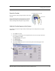


Table Of Contents
- Important Warnings
- Bio-Incompatibility Notice
- Compliance
- Introduction
- About this Guide
- Additional Detailed Documentation
- Contact Information
- Product Warranty
- Chapter 1
- Introduction
- Installation Checklist
- Installing Components
- Install the Central Server
- Install the Gateway
- Install Routers
- Place a Pendant into Survey Mode
- Determine Placement of Routers
- Quick Look Router
- Gateway/Router Reset Button
- LED Sequence
- Gateway/Router Channel Default
- Additional Gateway/Router Installation
- Changing Channels
- Router Depth
- Rebuild Subnet on Scanned Devices
- Scan Devices
- Chapter 2
- Introduction
- Transceiver Devices
- LED Light Indicator
- Installing Transceiver Devices
- Pull Cords/Emergency Call
- Check-in Pull Cord
- Pull Cord Transceiver with Extended Battery Pack
- Wall Mount Emergency Call
- Universal Transceiver
- Tamper
- Nurse Call
- Door/Window Transceiver
- Door/Window Transceiver with Reset Button
- PIR Sensor
- Smoke Detector
- Pendant Transceivers
- Activate the Battery
- Set up the Pendant
- Reset the Pendant
- Verify the Pendant Appears in the System
- Replace the Battery
- Test the System Operation
- Chapter 3
- Introduction
- Device Failure
- Router Failure
- Gateway Failure
- Chapter 4
- Specifications
- Power Cable Run Lengths
- Mesh Network Router/Gateway
- Quick Look Display for Quick Look Router
- Pendant Transceiver
- Pull Cord
- Nurse Call
- Door/Window Transceiver
- PIR Sensor
- Smoke Detector
- Universal Transceiver

Chapter 3: Maintenance
46 9600 Series Wireless Call System (0510-1078-D) - Hardware Installation Guide
Router Failure
When a full function device (Router) fails, its limited function device (i.e. Pull Cord, Universal) will fail to
communicate and automatically search for another Router upon a check-in or alarm.
To replace a failed Router
1. In the software application, click Report on the toolbar and open the Device Tree Report.
2. Sort the Device Tree Report by Comport and print the report.
3. Find the Router and all of its dependant Routers and make a list of these Routers (any Routers that
contain the defective Router name in their path).
4. Remove power from each Router noted in step 3.
a. If AC power is provided by a CPS, turn the CPS output off at this time (all Routers will report
low battery in 5 minutes, but that’s OK).
b. If AC power is provided by individual wall warts, unplug the wall wart for each Router noted
in step 3.
c. Remove battery power (turn battery slide switch to off position) for each Router noted in step
3.
5. In the software, delete all of the Routers noted in step 3 (check delete, click save).
6. Remove battery from each Pull Cord and Universal device that could possibly be within range of
the Routers noted in step 3.
7. Replace the defective Router.
8. Start with just the new Router for the steps below.
9. Apply power to the Router.
a. Apply battery power (turn battery slide switch to on position) for this Router.
b. If AC power is provided by a CPS, leave the CPS output off for now.
c. If AC power is provided by individual wall warts, also plug in the wall wart for this Router.
10. Perform a 15-second reset on this Router (refer to chapter 1 table x if necessary for a 15-second).
11. Wait for a visual indication Router joined the network (dual green blinks for several seconds).
12. Secure Router to the wall.
13. Repeat steps 9-11 for all remaining Routers noted in step 3 (important note: remaining Routers
must be done in order of shortest path to longest path based on the tree report from step 2).
14. Verify each Router noted in step 3 now appears in the software.
15. If AC power is provided by a CPS, re-enable the CPS output at this time.
16. Wait up to the supervision time for a Router and verify none of the Routers are reporting low
battery.