
User Manual
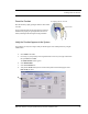
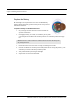


Table Of Contents
- Important Warnings
- Bio-Incompatibility Notice
- Compliance
- Introduction
- About this Guide
- Additional Detailed Documentation
- Contact Information
- Product Warranty
- Chapter 1
- Introduction
- Installation Checklist
- Installing Components
- Install the Central Server
- Install the Gateway
- Install Routers
- Place a Pendant into Survey Mode
- Determine Placement of Routers
- Quick Look Router
- Gateway/Router Reset Button
- LED Sequence
- Gateway/Router Channel Default
- Additional Gateway/Router Installation
- Changing Channels
- Router Depth
- Rebuild Subnet on Scanned Devices
- Scan Devices
- Chapter 2
- Introduction
- Transceiver Devices
- LED Light Indicator
- Installing Transceiver Devices
- Pull Cords/Emergency Call
- Check-in Pull Cord
- Pull Cord Transceiver with Extended Battery Pack
- Wall Mount Emergency Call
- Universal Transceiver
- Tamper
- Nurse Call
- Door/Window Transceiver
- Door/Window Transceiver with Reset Button
- PIR Sensor
- Smoke Detector
- Pendant Transceivers
- Activate the Battery
- Set up the Pendant
- Reset the Pendant
- Verify the Pendant Appears in the System
- Replace the Battery
- Test the System Operation
- Chapter 3
- Introduction
- Device Failure
- Router Failure
- Gateway Failure
- Chapter 4
- Specifications
- Power Cable Run Lengths
- Mesh Network Router/Gateway
- Quick Look Display for Quick Look Router
- Pendant Transceiver
- Pull Cord
- Nurse Call
- Door/Window Transceiver
- PIR Sensor
- Smoke Detector
- Universal Transceiver

9600 Series Wireless Call System (0510-1078-D) - Hardware Installation Guide 45
Chapter 3
Maintenance
Introduction
The 9600 Series network of devices is partially capable of self-maintenance in the event a device fails. The
system software has four data communications to aid in the maintenance of the network.
1. Reset—force individual Routers, all Routers on a single comports, or all Routers on all
comports to reset.
2. Scan—forces the Gateway and all its Routers to change channel or to execute a rebuild depending
upon what was configured.
3. Configure—individual device (name, supervision rate, channel, layer, etc.).
4. Delete—Remove individual devices from Router tables.
Device Failure
When a single, limited function end device (i.e. Pull Cord, Universal) fails, the following procedure will
remove it from the short address table and allow replacement.
To replace a failed end device
1. Unpower and physically remove the failed device.
2. Delete the device from the Configuration >>Devices window in the software. This results in a
broadcast command from the Gateway to remove this MAC short address for the Router table it
was joined to.
3. With the replacement device within range of the Router, remove the battery tab to activate the
device. The replacement device will automatically search all channels to find a “full function”
device to join.
4. Physically install the replacement device.
5. Alarm and then Reset the device. The system recognizes the device when it goes into alarm and
places it into the Device List for configuration.
6. Configure the replacement device in the software using the same device name as the failed device
previously deleted.
7. If necessary, configure the replacement device into a Unit.
8. If necessary, configure the replacement device into a Room.