
User Manual
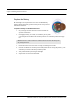


Table Of Contents
- Important Warnings
- Bio-Incompatibility Notice
- Compliance
- Introduction
- About this Guide
- Additional Detailed Documentation
- Contact Information
- Product Warranty
- Chapter 1
- Introduction
- Installation Checklist
- Installing Components
- Install the Central Server
- Install the Gateway
- Install Routers
- Place a Pendant into Survey Mode
- Determine Placement of Routers
- Quick Look Router
- Gateway/Router Reset Button
- LED Sequence
- Gateway/Router Channel Default
- Additional Gateway/Router Installation
- Changing Channels
- Router Depth
- Rebuild Subnet on Scanned Devices
- Scan Devices
- Chapter 2
- Introduction
- Transceiver Devices
- LED Light Indicator
- Installing Transceiver Devices
- Pull Cords/Emergency Call
- Check-in Pull Cord
- Pull Cord Transceiver with Extended Battery Pack
- Wall Mount Emergency Call
- Universal Transceiver
- Tamper
- Nurse Call
- Door/Window Transceiver
- Door/Window Transceiver with Reset Button
- PIR Sensor
- Smoke Detector
- Pendant Transceivers
- Activate the Battery
- Set up the Pendant
- Reset the Pendant
- Verify the Pendant Appears in the System
- Replace the Battery
- Test the System Operation
- Chapter 3
- Introduction
- Device Failure
- Router Failure
- Gateway Failure
- Chapter 4
- Specifications
- Power Cable Run Lengths
- Mesh Network Router/Gateway
- Quick Look Display for Quick Look Router
- Pendant Transceiver
- Pull Cord
- Nurse Call
- Door/Window Transceiver
- PIR Sensor
- Smoke Detector
- Universal Transceiver

9600 Series Wireless Call System (0510-1078-D) - Hardware Installation Guide 43
Test the System Operation
Test the System Operation
After all of the components that make up the 9600 Series Wireless Call System are in place, the system-wide
settings are applied, and information specific to at least one transceiver is entered into the database, test the
operation of the entire system. First, confirm that the software is responding; second, ensure that there is
sufficient coverage by the Routers; and third, test the operation of the Supervision function.
To test the software
1. At the Central Server, activate a Pendant transceiver by pressing the button. If the transceiver is
functioning properly, its green light will flash a series of times, indicating that it is sending a signal.
If the software is responding, an Alarm event will be listed on the Event List at the Central Server.
2. Reset the transceiver by rapidly pressing the button six times. The green light will flash each time
the button is pressed. If the transceiver is reset properly, the green light will flash a series of times,
indicating that the Reset signal is being transmitted.
If the software is responding, a Reset event will be listed on the Event List at the Central Server.
To test the system for sufficient coverage
1. At a remote location in the facility, activate a Pendant transceiver by pressing the button. If the
transceiver is functioning properly, its green light will flash a series of times, indicating that it is
sending a signal.
If there is sufficient coverage by the Routers, an Alarm event will be listed on the Event List at the
Central Server.
If your facility is using a paging system in conjunction with your 9600 Series Wireless Call System,
an Alarm message will be received by the pager.
2. Again at a remote location, reset the transceiver by rapidly pressing the button six times. The green
light will flash each time the button is pressed. If the transceiver is reset properly, the green light
will flash a series of times, indicating that the Reset signal is being transmitted.
If there is sufficient coverage by the Routers, a Reset event will be listed on the Event List at the
Central Server.
If your facility is using a paging system in conjunction with your 9600 Series Wireless Call System,
a Reset message will be received by the pager.
3. Repeat these steps at several locations to ensure that the transceiver’s signal is received from all
areas.
To test the operation of the Supervision function
1. Confirm that all of the supervision settings are defined. Refer to the section entitled “Configure
Units” in the Series 6.0 Software Administrator Guide (PN 0510-1080). Make a note of the number
of minutes selected for Transmitter Supervised Time.
2. Confirm that the Supervision setting is enabled for the transceiver(s) used for testing. Refer to the
“Admit” section in the Series 6.0 Software User Guide (PN 0510-1079).
3. Place a number of Pendant transceivers in remote locations throughout the facility.
4. If the Supervision function is operating properly and coverage is adequate, none of the devices will
issue a Missing event at the Central Server.