
User Manual
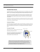
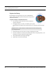


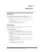


Table Of Contents
- Important Warnings
- Bio-Incompatibility Notice
- Compliance
- Introduction
- About this Guide
- Additional Detailed Documentation
- Contact Information
- Product Warranty
- Chapter 1
- Introduction
- Installation Checklist
- Installing Components
- Install the Central Server
- Install the Gateway
- Install Routers
- Place a Pendant into Survey Mode
- Determine Placement of Routers
- Quick Look Router
- Gateway/Router Reset Button
- LED Sequence
- Gateway/Router Channel Default
- Additional Gateway/Router Installation
- Changing Channels
- Router Depth
- Rebuild Subnet on Scanned Devices
- Scan Devices
- Chapter 2
- Introduction
- Transceiver Devices
- LED Light Indicator
- Installing Transceiver Devices
- Pull Cords/Emergency Call
- Check-in Pull Cord
- Pull Cord Transceiver with Extended Battery Pack
- Wall Mount Emergency Call
- Universal Transceiver
- Tamper
- Nurse Call
- Door/Window Transceiver
- Door/Window Transceiver with Reset Button
- PIR Sensor
- Smoke Detector
- Pendant Transceivers
- Activate the Battery
- Set up the Pendant
- Reset the Pendant
- Verify the Pendant Appears in the System
- Replace the Battery
- Test the System Operation
- Chapter 3
- Introduction
- Device Failure
- Router Failure
- Gateway Failure
- Chapter 4
- Specifications
- Power Cable Run Lengths
- Mesh Network Router/Gateway
- Quick Look Display for Quick Look Router
- Pendant Transceiver
- Pull Cord
- Nurse Call
- Door/Window Transceiver
- PIR Sensor
- Smoke Detector
- Universal Transceiver

Chapter 2: Installing Transceiver Devices
40 9600 Series Wireless Call System (0510-1078-D) - Hardware Installation Guide
Pendant Transceivers
The Pendant transceiver is a wireless, mobile transceiver that can be worn around the neck or wrist, or
attached to a belt. The protective boot protects the Pendant transceiver against dropping and water ingress.
However to prevent water damage, avoid prolonged submersion and direct contact with a water stream.
The Pendant has one (1) light that is visible from the outside of the enclosure. The light flashes 3 times in
rapid succession when the alarm is triggered or cleared. A green light indicates communication with the
Gateway/Router is good; red indicates communication failure and the device is not able to transmit to the
Gateway/Router.
The Pendant can be supervised; if no information is received by the system from the Gateway for a specified
supervision time, a Check Transmitter alarm is generated in the Event List at the computer. Since the Pendant
is a mobile device, no installation is required.
Activate the Battery
The Pendant is shipped with a replaceable 3V battery. To activate the battery, use your fingers to remove the
back cover and pull off the plastic battery tab. Be sure the battery stays in the battery holder while the plastic
tab is pulled. Additionally, make certain that you are not pressing on the blue button while activating the
battery.
Set up the Pendant
With the Pendant transceiver within range of the system, activate
the Pendant by pressing the blue button.
If the transceiver is working properly, the green light will flash a
series of times, indicating that the Alarm signal is being
transmitted. The system senses the Pendant when it goes into
alarm and adds it to its list of available devices.
NOTE: The default channel for Gateway/Router installation is channel 25. The Pendant will
start its search for a Gateway/Router parent on channel 25. If where you activate the
transceiver is not in the vicinity of channel 25, a series of red light flashes will occur for 2
minutes then the Pendant will search all channels to find a Gateway/Router parent. Once
communication is established a series of green light flashes occur.
Press for
1
/
2
second
3 green flashes