
User Manual
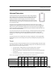
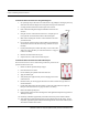
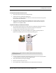


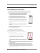


Table Of Contents
- Important Warnings
- Bio-Incompatibility Notice
- Compliance
- Introduction
- About this Guide
- Additional Detailed Documentation
- Contact Information
- Product Warranty
- Chapter 1
- Introduction
- Installation Checklist
- Installing Components
- Install the Central Server
- Install the Gateway
- Install Routers
- Place a Pendant into Survey Mode
- Determine Placement of Routers
- Quick Look Router
- Gateway/Router Reset Button
- LED Sequence
- Gateway/Router Channel Default
- Additional Gateway/Router Installation
- Changing Channels
- Router Depth
- Rebuild Subnet on Scanned Devices
- Scan Devices
- Chapter 2
- Introduction
- Transceiver Devices
- LED Light Indicator
- Installing Transceiver Devices
- Pull Cords/Emergency Call
- Check-in Pull Cord
- Pull Cord Transceiver with Extended Battery Pack
- Wall Mount Emergency Call
- Universal Transceiver
- Tamper
- Nurse Call
- Door/Window Transceiver
- Door/Window Transceiver with Reset Button
- PIR Sensor
- Smoke Detector
- Pendant Transceivers
- Activate the Battery
- Set up the Pendant
- Reset the Pendant
- Verify the Pendant Appears in the System
- Replace the Battery
- Test the System Operation
- Chapter 3
- Introduction
- Device Failure
- Router Failure
- Gateway Failure
- Chapter 4
- Specifications
- Power Cable Run Lengths
- Mesh Network Router/Gateway
- Quick Look Display for Quick Look Router
- Pendant Transceiver
- Pull Cord
- Nurse Call
- Door/Window Transceiver
- PIR Sensor
- Smoke Detector
- Universal Transceiver

Chapter 2: Installing Transceiver Devices
38 9600 Series Wireless Call System (0510-1078-D) - Hardware Installation Guide
7. Mount the base of the enclosure to the wall using two drywall
screws.
8. If necessary, insert the 3V battery (see “To replace the battery
in a PIR Sensor”).
9. Replace the electronic assembly.
10. Replace the sensor lens cap.
To set up the PIR Sensor for use
1. Activate the PIR Sensor by placing it in alarm (walk in the
motion detection area of the sensor).
2. If the PIR Sensor is working properly, the Central Server will sense the PIR Sensor when it goes
into alarm and add it to its list of devices.
3. The alarm resets once motion is no longer detected in the detection area.
4. At the Central Server, update the PIR Sensor information, for example, giving it a name and/or
assigning it to a room or unit. Refer to the “Update Devices” section in the Series 6.0 Software
Administrator Guide (PN 0510-1080).
To replace the battery in a PIR Sensor
1. With the PIR Sensor facing you, remove the sensor lens cap from the
base the sensor.
2. Using a small Phillips head screwdriver, remove the electronic assembly
enclosure.
3. Remove the old battery.
4. Insert the 3V battery into the battery holder. Be sure to align the positive
(+) end of the battery as marked on the battery holder.
5. Replace the electronic assembly enclosure.
6. Replace the sensor lens cap.
Mounting
holes