
User Manual
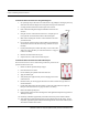
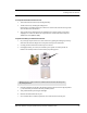


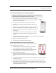


Table Of Contents
- Important Warnings
- Bio-Incompatibility Notice
- Compliance
- Introduction
- About this Guide
- Additional Detailed Documentation
- Contact Information
- Product Warranty
- Chapter 1
- Introduction
- Installation Checklist
- Installing Components
- Install the Central Server
- Install the Gateway
- Install Routers
- Place a Pendant into Survey Mode
- Determine Placement of Routers
- Quick Look Router
- Gateway/Router Reset Button
- LED Sequence
- Gateway/Router Channel Default
- Additional Gateway/Router Installation
- Changing Channels
- Router Depth
- Rebuild Subnet on Scanned Devices
- Scan Devices
- Chapter 2
- Introduction
- Transceiver Devices
- LED Light Indicator
- Installing Transceiver Devices
- Pull Cords/Emergency Call
- Check-in Pull Cord
- Pull Cord Transceiver with Extended Battery Pack
- Wall Mount Emergency Call
- Universal Transceiver
- Tamper
- Nurse Call
- Door/Window Transceiver
- Door/Window Transceiver with Reset Button
- PIR Sensor
- Smoke Detector
- Pendant Transceivers
- Activate the Battery
- Set up the Pendant
- Reset the Pendant
- Verify the Pendant Appears in the System
- Replace the Battery
- Test the System Operation
- Chapter 3
- Introduction
- Device Failure
- Router Failure
- Gateway Failure
- Chapter 4
- Specifications
- Power Cable Run Lengths
- Mesh Network Router/Gateway
- Quick Look Display for Quick Look Router
- Pendant Transceiver
- Pull Cord
- Nurse Call
- Door/Window Transceiver
- PIR Sensor
- Smoke Detector
- Universal Transceiver

9600 Series Wireless Call System (0510-1078-D) - Hardware Installation Guide 37
Installing Transceiver Devices
To set up the Door/Window transceiver for use
1. Activate the Door/Window transceiver by opening the door or window.
If the transceiver is working properly, the Central Server will sense the Door/Window transceiver
when it goes into alarm and add it to its list of devices.
2. Reset the Door/Window transceiver by closing the door or window and pressing the reset button if
applicable.
3. At the Central Server, update the Door/Window transceiver information, for example, giving it a
name and/or assigning it to a room or unit. Be sure to enable the Inactivity Check-In feature and
select beginning and end times. Refer to the “Update Devices” section in the Series 6.0 Software
Administrator Guide (PN 0510-1080).
PIR Sensor
The Passive Infrared (PIR) Sensor is a passive infrared motion detector that senses
motion in a room or hallway. An Assistance Required alarm event is reported in the
Event List each time the detector is activated.
A PIR Sensor can be supervised; a routine signal is sent from the device and if the signal
is not received by the system, a Device Fault event is generated in the Event List at the
computer. The PIR Sensor is powered by a replaceable 3V battery within the Universal
enclosure.
To mount the PIR Sensor
1. Remove the sensor lens cap from the base the sensor.
2. Using a small Phillips head screwdriver, remove the electronic
assembly enclosure.
3. Hold the base of the PIR Sensor enclosure against the wall at
the desired mounting height.
4. Mark the location of the two mounting holes.
5. Drill holes where the marks were made.
If the drilled holes do not hit a stud wall, you must use wall
anchors.
6. Line up the holes on the base of the enclosure with the newly
drilled holes.
NOTE: More specific mounting and testing specifications can be found in the
manufacturer’s instructions (included with the product).
NOTE: The Universal transceiver integrates with the PIR Sensor. Refer to “Universal
Transceiver” on page 29for information on the LED light, tamper functionality and
replacing the battery.
Unscrew here