
User Manual
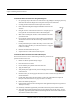
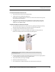


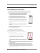


Table Of Contents
- Important Warnings
- Bio-Incompatibility Notice
- Compliance
- Introduction
- About this Guide
- Additional Detailed Documentation
- Contact Information
- Product Warranty
- Chapter 1
- Introduction
- Installation Checklist
- Installing Components
- Install the Central Server
- Install the Gateway
- Install Routers
- Place a Pendant into Survey Mode
- Determine Placement of Routers
- Quick Look Router
- Gateway/Router Reset Button
- LED Sequence
- Gateway/Router Channel Default
- Additional Gateway/Router Installation
- Changing Channels
- Router Depth
- Rebuild Subnet on Scanned Devices
- Scan Devices
- Chapter 2
- Introduction
- Transceiver Devices
- LED Light Indicator
- Installing Transceiver Devices
- Pull Cords/Emergency Call
- Check-in Pull Cord
- Pull Cord Transceiver with Extended Battery Pack
- Wall Mount Emergency Call
- Universal Transceiver
- Tamper
- Nurse Call
- Door/Window Transceiver
- Door/Window Transceiver with Reset Button
- PIR Sensor
- Smoke Detector
- Pendant Transceivers
- Activate the Battery
- Set up the Pendant
- Reset the Pendant
- Verify the Pendant Appears in the System
- Replace the Battery
- Test the System Operation
- Chapter 3
- Introduction
- Device Failure
- Router Failure
- Gateway Failure
- Chapter 4
- Specifications
- Power Cable Run Lengths
- Mesh Network Router/Gateway
- Quick Look Display for Quick Look Router
- Pendant Transceiver
- Pull Cord
- Nurse Call
- Door/Window Transceiver
- PIR Sensor
- Smoke Detector
- Universal Transceiver

Chapter 2: Installing Transceiver Devices
36 9600 Series Wireless Call System (0510-1078-D) - Hardware Installation Guide
Door/Window Transceiver with Reset Button
If your Door/Window transceiver comes with a reset button, the alarm must be
reset at the door by pressing the reset button once the door/window is closed. The
Door/Window transceiver comes in three pieces: the transceiver enclosure, a
magnet and a reset button. There are two types of reset buttons.
To mount the Door/Window transceiver with Reset Button
1. Mount the Door/Window magnet (refer to “To mount the Door/Window
magnet to the door or window” on page 34). The distance between the
reed switch in the transceiver and the magnet must be no more than 1/2
inch.
2. Mount the Door/Window transceiver (refer to “To mount the Door/
Window transceivers with adhesive pad” on page 35 or “To mount the
Door/Window transceivers with adhesive pad” on page 35). Orientate
the internal reed switch next to the magnet 3/8 inch away.
3. Mount the reset button.
To mount the Reset buttons
There are two types of reset buttons. The Universal transceiver comes pre-wired with 4 feet of 2-
conductor 22 gauge wire. Route wire into door or window jamb and to desired reset button
location.
1. To mount the reset button that has the round push button:
a. Use your fingers to remove the front cover.
b. Using the base of the reset button as a template, place it level against the door or
wall and mark the location of the two mounting holes.
c. Drill holes where you made the marks.
d. Line up the holes on the base of the reset button with the newly drilled holes and
mount the base using the screws provided.
e. Snap the front cover of the reset button back onto the base.
2. To mount the reset button that is labeled EMERGENCY:
a. Using the reset button as a template, place it level against the wall or door and mark
the location of the two mounting holes.
b. Drill holes where you made the marks.
c. Line up the holes on the base of the reset button with the newly drilled holes and
mount the reset button using the screws provided.