
User Manual


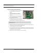
Table Of Contents
- Important Warnings
- Bio-Incompatibility Notice
- Compliance
- Introduction
- About this Guide
- Additional Detailed Documentation
- Contact Information
- Product Warranty
- Chapter 1
- Introduction
- Installation Checklist
- Installing Components
- Install the Central Server
- Install the Gateway
- Install Routers
- Place a Pendant into Survey Mode
- Determine Placement of Routers
- Quick Look Router
- Gateway/Router Reset Button
- LED Sequence
- Gateway/Router Channel Default
- Additional Gateway/Router Installation
- Changing Channels
- Router Depth
- Rebuild Subnet on Scanned Devices
- Scan Devices
- Chapter 2
- Introduction
- Transceiver Devices
- LED Light Indicator
- Installing Transceiver Devices
- Pull Cords/Emergency Call
- Check-in Pull Cord
- Pull Cord Transceiver with Extended Battery Pack
- Wall Mount Emergency Call
- Universal Transceiver
- Tamper
- Nurse Call
- Door/Window Transceiver
- Door/Window Transceiver with Reset Button
- PIR Sensor
- Smoke Detector
- Pendant Transceivers
- Activate the Battery
- Set up the Pendant
- Reset the Pendant
- Verify the Pendant Appears in the System
- Replace the Battery
- Test the System Operation
- Chapter 3
- Introduction
- Device Failure
- Router Failure
- Gateway Failure
- Chapter 4
- Specifications
- Power Cable Run Lengths
- Mesh Network Router/Gateway
- Quick Look Display for Quick Look Router
- Pendant Transceiver
- Pull Cord
- Nurse Call
- Door/Window Transceiver
- PIR Sensor
- Smoke Detector
- Universal Transceiver

Chapter 2: Installing Transceiver Devices
26 9600 Series Wireless Call System (0510-1078-D) - Hardware Installation Guide
To replace the battery to the Pull Cord
1. Use a small Phillips screwdriver to remove the front cover
of the Pull Cord from its wall mounting.
2. Grip the battery holder and use a small flat screwdriver to
hold back the top circuit board retainer clip.
3. Gently pry up that corner of the circuit board past the
retaining clip. Repeat for the second retaining clip and
remove the circuit board.
4. If changing the battery, use a small, non-conductive piece
of plastic or wood to push the 3V Lithium coin cell battery
from the rear of the battery clip until it comes free.
5. Insert the new 3V Lithium coin cell battery into the battery holder. Be sure to align the positive (+)
end of the battery as marked on the battery and battery holder.
6. Verify communication by observing the LED light.
7. Once communication is verified, return the circuit board into the enclosure, slide the left edge of the
circuit board under the two lower retaining clips then lower the top end down and gently push until
it snaps under the two upper retaining clips.
8. Replace the front cover of the Pull Cord to its wall mounting.
To replace the AA Batteries for the Pull Cord with Extended Life Battery Pack
1. Remove the Pull Cord Assembly from its enclosure.
2. Grip the battery holder and pull all four batteries free from the battery holder.
3. Insert four new AA Lithium Ion batteries into the battery holder.
4. Verify communication by observing the LED on the Pull Cord circuit board.
5. Once communication is verified replace the rear cover of the Pull Cord and remount it to the surface or
flush mount enclosure.
NOTE: Do not use a metal screwdriver or metallic instrument to remove the battery. This
may damage the device.
NOTE: Do not use a metal screwdriver or metallic instrument to remove the battery. This
may damage the device.
Retaining Clips