
User Manual


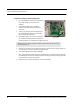
Table Of Contents
- Important Warnings
- Bio-Incompatibility Notice
- Compliance
- Introduction
- About this Guide
- Additional Detailed Documentation
- Contact Information
- Product Warranty
- Chapter 1
- Introduction
- Installation Checklist
- Installing Components
- Install the Central Server
- Install the Gateway
- Install Routers
- Place a Pendant into Survey Mode
- Determine Placement of Routers
- Quick Look Router
- Gateway/Router Reset Button
- LED Sequence
- Gateway/Router Channel Default
- Additional Gateway/Router Installation
- Changing Channels
- Router Depth
- Rebuild Subnet on Scanned Devices
- Scan Devices
- Chapter 2
- Introduction
- Transceiver Devices
- LED Light Indicator
- Installing Transceiver Devices
- Pull Cords/Emergency Call
- Check-in Pull Cord
- Pull Cord Transceiver with Extended Battery Pack
- Wall Mount Emergency Call
- Universal Transceiver
- Tamper
- Nurse Call
- Door/Window Transceiver
- Door/Window Transceiver with Reset Button
- PIR Sensor
- Smoke Detector
- Pendant Transceivers
- Activate the Battery
- Set up the Pendant
- Reset the Pendant
- Verify the Pendant Appears in the System
- Replace the Battery
- Test the System Operation
- Chapter 3
- Introduction
- Device Failure
- Router Failure
- Gateway Failure
- Chapter 4
- Specifications
- Power Cable Run Lengths
- Mesh Network Router/Gateway
- Quick Look Display for Quick Look Router
- Pendant Transceiver
- Pull Cord
- Nurse Call
- Door/Window Transceiver
- PIR Sensor
- Smoke Detector
- Universal Transceiver

9600 Series Wireless Call System (0510-1078-D) - Hardware Installation Guide 25
Installing Transceiver Devices
To flush mount the Transceiver
1. Hold the base of the flush mount enclosure against the wall at the desired mounting height and trace
the outline of the flush mount enclosure.
2. Cutout the hole along the traced lines.
3. Insert the flush mount enclosure into the hole and secure in place by routing the wall mounting
flaps outward and tight against the inside surface of the drywall.
4. Determine the desired length of the pull cord string. The standard length of a Pull Cord strings is six
feet long. However, as mounting heights vary, the length of the string may need to be adjusted.
5. In order for the battery pack to fit into the single gang box the two halves that hold the batteries
need to be folded in half. To do this remove the liner from the tape strip on the back side of the
Extended Life Battery Pack and slowly fold the two halves together in order to adhere one half to
the other.
6. Connect the battery pack to the pigtail connector on the Pull Cord assembly.
7. Make certain that the pigtail wires leading from the Pull Cord Assembly pass through the cutout in
the back enclosure cover and that they are not pinched.
8. Place the pull cord assembly aligned over the mating holes in the flush mount enclosure and secure
in place with the two screws provided.
To set up the Pull Cord for use
1. Activate the Pull Cord by pulling the cord.
If the transceiver is working properly, the Central Server will sense the transceiver when it goes into
alarm and add it to its list of devices.
2. Reset the Pull Cord by rotating the red HELP lever back to the UP position.
3. At the Central Server, update the Pull Cord information, for example, giving the Pull Cord a name
and/or assigning it to a room or unit. Refer to the “Update Devices” section in the Series 6.0
Software Administrator Guide (PN 0510-1080).
NOTE: Do not over tighten the screws as this will cause the alarm lever to bind and thus
not release correctly.