
User Manual


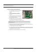
Table Of Contents
- Important Warnings
- Bio-Incompatibility Notice
- Compliance
- Introduction
- About this Guide
- Additional Detailed Documentation
- Contact Information
- Product Warranty
- Chapter 1
- Introduction
- Installation Checklist
- Installing Components
- Install the Central Server
- Install the Gateway
- Install Routers
- Place a Pendant into Survey Mode
- Determine Placement of Routers
- Quick Look Router
- Gateway/Router Reset Button
- LED Sequence
- Gateway/Router Channel Default
- Additional Gateway/Router Installation
- Changing Channels
- Router Depth
- Rebuild Subnet on Scanned Devices
- Scan Devices
- Chapter 2
- Introduction
- Transceiver Devices
- LED Light Indicator
- Installing Transceiver Devices
- Pull Cords/Emergency Call
- Check-in Pull Cord
- Pull Cord Transceiver with Extended Battery Pack
- Wall Mount Emergency Call
- Universal Transceiver
- Tamper
- Nurse Call
- Door/Window Transceiver
- Door/Window Transceiver with Reset Button
- PIR Sensor
- Smoke Detector
- Pendant Transceivers
- Activate the Battery
- Set up the Pendant
- Reset the Pendant
- Verify the Pendant Appears in the System
- Replace the Battery
- Test the System Operation
- Chapter 3
- Introduction
- Device Failure
- Router Failure
- Gateway Failure
- Chapter 4
- Specifications
- Power Cable Run Lengths
- Mesh Network Router/Gateway
- Quick Look Display for Quick Look Router
- Pendant Transceiver
- Pull Cord
- Nurse Call
- Door/Window Transceiver
- PIR Sensor
- Smoke Detector
- Universal Transceiver

9600 Series Wireless Call System (0510-1078-D) - Hardware Installation Guide 23
Installing Transceiver Devices
Check-in Pull Cord
A Check-in Pull Cord enables the staff or patient to push a green button to check-in. Pressing the green button
indicates to the system that the patient has checked in or been visited by staff. The type of check-in depends
on how your Pull Cord is configured, refer to the Series 6.0 Software Administrator Guide (PN 0510-1080).
Check-in types
• Patient Check In—A patient pushes the button to notify the staff that he/she is awake and does not
require assistance.
• Staff Check In—A staff member pushes the check-in button once they have checked on a patient.
• Staff Care Complete—A staff member pushes the check-in button in response to an Assistance
Required alarm once the patient has been checked on and the alarming device is reset. If JCAHO is
enforced, this will clear the White alarm from the Client computer
To mount the Pull Cord transceiver
1. Using the rear plate of the Pull Cord as a template, place it level against the wall at the desired
mounting height and mark the location of the two mounting holes. A height of 48 inches is
standard.
2. Center punch each hole and install two nylon wall anchors (included). If the Pull Cord is located on
a concrete wall then you must use the wall anchors designed for use with concrete (not included).
Make certain that wall anchors are installed straight and flush to the face of the wall. If not this will
cause the alarm lever to bind and thus not release correctly.
3. Determine the desired length of the red Pull Cord string. The standard length of a Pull Cord strings
is six feet long. However, as mounting heights vary, the length of the string may need to be
adjusted.
To adjust the length of the Pull Cord string:
a. Gently pop the red alarm lever free from the enclosure and remove the string.
b. Cut the string to the desired length and rewind it on the alarm lever in the reverse order it was
removed. There are instructions printed on the side of the red alarm lever for assistance in
winding the string.
c. Press the red alarm lever back onto the enclosure and route the pull cord string through the
small slit in the bottom corner of the enclosure.
4. Pull the plastic battery tab to activate the battery or refer to the section entitled “To replace the
battery to the Emergency Call” on page 28 to insert a new battery.
5. Place the rear plate of the Pull Cord into the recess on the back of the transceiver enclosure.
6. Place the Pull Cord assembly over the wall anchors in alignment with the holes in the enclosure and
insert two screws (included).
NOTE: Do not over tighten the screws as this will cause the alarm lever to bind and thus
not release correctly.