
User Manual


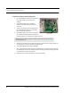
Table Of Contents
- Important Warnings
- Bio-Incompatibility Notice
- Compliance
- Introduction
- About this Guide
- Additional Detailed Documentation
- Contact Information
- Product Warranty
- Chapter 1
- Introduction
- Installation Checklist
- Installing Components
- Install the Central Server
- Install the Gateway
- Install Routers
- Place a Pendant into Survey Mode
- Determine Placement of Routers
- Quick Look Router
- Gateway/Router Reset Button
- LED Sequence
- Gateway/Router Channel Default
- Additional Gateway/Router Installation
- Changing Channels
- Router Depth
- Rebuild Subnet on Scanned Devices
- Scan Devices
- Chapter 2
- Introduction
- Transceiver Devices
- LED Light Indicator
- Installing Transceiver Devices
- Pull Cords/Emergency Call
- Check-in Pull Cord
- Pull Cord Transceiver with Extended Battery Pack
- Wall Mount Emergency Call
- Universal Transceiver
- Tamper
- Nurse Call
- Door/Window Transceiver
- Door/Window Transceiver with Reset Button
- PIR Sensor
- Smoke Detector
- Pendant Transceivers
- Activate the Battery
- Set up the Pendant
- Reset the Pendant
- Verify the Pendant Appears in the System
- Replace the Battery
- Test the System Operation
- Chapter 3
- Introduction
- Device Failure
- Router Failure
- Gateway Failure
- Chapter 4
- Specifications
- Power Cable Run Lengths
- Mesh Network Router/Gateway
- Quick Look Display for Quick Look Router
- Pendant Transceiver
- Pull Cord
- Nurse Call
- Door/Window Transceiver
- PIR Sensor
- Smoke Detector
- Universal Transceiver

Chapter 2: Installing Transceiver Devices
22 9600 Series Wireless Call System (0510-1078-D) - Hardware Installation Guide
LED Light Indicator
The Pendant, Pull Cord and Universal transceivers contain a two-color indicator light. In general, green
indicates good and red indicates bad.
No light—if the LED indicator does not blink within a few seconds of alarming or clearing an alarm,
this may indicate a dead battery; try replacing the battery. If the problem persists, contact Technical
Support.
3 green blinks—alarm, clear, or check-in had been transmitted and a confirmation has been received
from the Gateway.
10 green blinks—device has successfully received new configuration data from the computer.
1 green blink—alarm, clear or check-in has been transmitted but the device has not yet received a
confirmation from the Gateway. Wait up to 15 seconds for the device to try again by itself; do not re-
alarm the device. The Pendant will also blink green once each time the blue button is pressed; as visual
feedback that the button press was recognized.
1 red blink—device cannot find a Router to communicate with; device may be out of range or on the
wrong channel.
2 red blinks—join failed; the device found one or more Routers, but Routers indicate they cannot
accept any additional devices. An additional Router may need to be added to support a large number of
devices in the same area.
Installing Transceiver Devices
Pull Cords/Emergency Call
A Pull Cord is usually mounted on the wall. This device is used to request staff assistance
and is commonly used in bedrooms and bathrooms. It is suitable for use in close
proximity to showers or baths; however to prevent damage, avoid any submersion.
The Pull Cord has one (1) LED light. The light is visible when the enclosure is open (i.e.
during installation), but not visible during normal operation when the enclosure is closed.
The light flashes briefly once every check-in (20 minutes by default), once each time the
device alarm is triggered or cleared, and once when the optional check-in button is
pressed. Green indicates that communication with the Router is good; red indicates
communication failure and the device is not able to transmit to the Router.
An Assistance Required alarm event is reported in the Event List when a patient pulls the
cord. The Pull Cord is supervised; a routine signal is sent from the transceiver and if the
signal is not received by the system, a Device Fault event is generated in the Event List at
the computer.