
User Manual

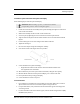

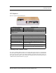

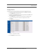

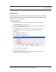
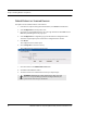
Table Of Contents
- Important Warnings
- Bio-Incompatibility Notice
- Compliance
- Introduction
- About this Guide
- Additional Detailed Documentation
- Contact Information
- Product Warranty
- Chapter 1
- Introduction
- Installation Checklist
- Installing Components
- Install the Central Server
- Install the Gateway
- Install Routers
- Place a Pendant into Survey Mode
- Determine Placement of Routers
- Quick Look Router
- Gateway/Router Reset Button
- LED Sequence
- Gateway/Router Channel Default
- Additional Gateway/Router Installation
- Changing Channels
- Router Depth
- Rebuild Subnet on Scanned Devices
- Scan Devices
- Chapter 2
- Introduction
- Transceiver Devices
- LED Light Indicator
- Installing Transceiver Devices
- Pull Cords/Emergency Call
- Check-in Pull Cord
- Pull Cord Transceiver with Extended Battery Pack
- Wall Mount Emergency Call
- Universal Transceiver
- Tamper
- Nurse Call
- Door/Window Transceiver
- Door/Window Transceiver with Reset Button
- PIR Sensor
- Smoke Detector
- Pendant Transceivers
- Activate the Battery
- Set up the Pendant
- Reset the Pendant
- Verify the Pendant Appears in the System
- Replace the Battery
- Test the System Operation
- Chapter 3
- Introduction
- Device Failure
- Router Failure
- Gateway Failure
- Chapter 4
- Specifications
- Power Cable Run Lengths
- Mesh Network Router/Gateway
- Quick Look Display for Quick Look Router
- Pendant Transceiver
- Pull Cord
- Nurse Call
- Door/Window Transceiver
- PIR Sensor
- Smoke Detector
- Universal Transceiver

9600 Series Wireless Call System (0510-1078-D) - Hardware Installation Guide 13
Installing Components
LED Sequence
Below is an explanation of the LED sequence.
Gateway/Router Channel Default
The Gateway and Router default to channel 25. In a facility with a single Gateway, it is recommended to
leave the Gateway and Routers on channel 25. In a facility with multiple Gateways, it is recommended to
power-up only one Gateway system at a time during installation. Once the first Gateway/Router system is up
and running, switch that system to another channel, then commission the next Gateway system (refer to
“Additional Gateway/Router Installation” on page 14).
LED Power Up Sequence Explanation of LED
L1, L2, L3, L4 (sequentially) Device executing normal firmware.
All LEDs On (not maintained) Device executing normal firmware.
NOTE: If power up sequence does not occur and the green light is blinking every second, than the device is in
manufacturer’s mode.
LED Display Sequence Explanation of LED
Dual Green LED Flash (10 times) Device is attempting to identify a Router/Gateway parent.
Single Green LED Flash (L2) Successfully joined with and checked in with identified parent.
Single Red LED Flash (L1) No response from identified parent.
Repeating (dim) Red LED Flash (L3) Device operating normally, flashes once per second (heart beat sequence).
Dual Green LED Flash (one time) Router/Gateway Successfully forwarded packet from a child to the
Central Server or display.
Single Green LED Flash (L4) Gateway received the check in message sent by Server every 15 seconds.
L3 and L4 Solid Illumination Battery switch turned off or battery fully discharged and requiring the
9600 Series Router Battery Recharger procedure (PN 0510-0336).
L4
L3
L2
L1