
User Manual


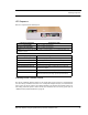


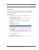
Table Of Contents
- Important Warnings
- Bio-Incompatibility Notice
- Compliance
- Introduction
- About this Guide
- Additional Detailed Documentation
- Contact Information
- Product Warranty
- Chapter 1
- Introduction
- Installation Checklist
- Installing Components
- Install the Central Server
- Install the Gateway
- Install Routers
- Place a Pendant into Survey Mode
- Determine Placement of Routers
- Quick Look Router
- Gateway/Router Reset Button
- LED Sequence
- Gateway/Router Channel Default
- Additional Gateway/Router Installation
- Changing Channels
- Router Depth
- Rebuild Subnet on Scanned Devices
- Scan Devices
- Chapter 2
- Introduction
- Transceiver Devices
- LED Light Indicator
- Installing Transceiver Devices
- Pull Cords/Emergency Call
- Check-in Pull Cord
- Pull Cord Transceiver with Extended Battery Pack
- Wall Mount Emergency Call
- Universal Transceiver
- Tamper
- Nurse Call
- Door/Window Transceiver
- Door/Window Transceiver with Reset Button
- PIR Sensor
- Smoke Detector
- Pendant Transceivers
- Activate the Battery
- Set up the Pendant
- Reset the Pendant
- Verify the Pendant Appears in the System
- Replace the Battery
- Test the System Operation
- Chapter 3
- Introduction
- Device Failure
- Router Failure
- Gateway Failure
- Chapter 4
- Specifications
- Power Cable Run Lengths
- Mesh Network Router/Gateway
- Quick Look Display for Quick Look Router
- Pendant Transceiver
- Pull Cord
- Nurse Call
- Door/Window Transceiver
- PIR Sensor
- Smoke Detector
- Universal Transceiver

Chapter 1: Installing Hardware Components
12 9600 Series Wireless Call System (0510-1078-D) - Hardware Installation Guide
Gateway/Router Reset Button
The Router has four types of reset. Respectively, the Gateway supports the first three. By using the reset
button on the bottom edge of the Router/Gateway you can perform the resets described in the chart below.
Solid Red Flashing Green
Non-illuminated
Solid Green
Action Upon Release of Reset Button
Reset
Type
To Execute Press
and Hold Reset
Button
Release Reset
Button When
LED Illuminates
Associated
(child)
End-
devices
Associated
(child)
Routers
Routing
Table
Device
Name Channel
LED Sequence After Release of Reset
Button
1-second Hold until 1 LED
comes on solid
(about 1 second)
No change No change Clear No
change
Same 1.
2.
3.
4.
L1, L2, L3, L4 (sequentially)
All LEDs on
Green LEDs flash
Single green flash if
communication is successful
5-second Hold until 2 LED
comes on solid
(about 5 seconds)
Clear
No change
1
Clear No
change
Same 1.
2.
3.
4.
L1, L2, L3, L4 (sequentially)
All LEDs on
Green LEDs flash
Single green flash if
communication is successful
10-second Hold until 3 LED
comes on solid
(about 10 seconds)
Clear Clear Clear
Default
2
25 1.
2.
3.
4.
L1, L2, L3, L4 (sequentially)
All LEDs on
Green LEDs flash
Single green flash if
communication is successful
15-second Hold until 4 LED
comes on solid
(about 15 seconds)
Clear Clear Clear
Default
2
Scan
3
1.
2.
3.
4.
5.
6.
L1, L2, L3, L4 (sequentially)
All LEDs on
No LED activity for 30 seconds
while channels are scanned
Green LEDs flash
Blink red RF 30 seconds
Single green LED flash and red RF
LED flashes for 15 seconds
1
If a Router/Gateway does not have child Routers (at the end of a branch in the tree structure), a 5-second reset will cause the Router/
Gateway to leave the network, and then rejoin the network. On the Router, this is indicated by observing the L2 flash off and back on
after 5 seconds.
2
A 10-second or 15 second reset will cause a Router/Gateway name to revert to factory default; Rout-xxxx/Gatexxxx, where xxxx
are the last 4 characters of the Router/Gateway MAC ID.
3
The Router will scan all channels and will join the first channel that replied with the highest RSSI (and stay on that channel
indefinitely).