
User Manual


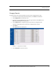

Table Of Contents
- Important Warnings
- Bio-Incompatibility Notice
- Compliance
- Introduction
- About this Guide
- Additional Detailed Documentation
- Contact Information
- Product Warranty
- Chapter 1
- Introduction
- Installation Checklist
- Installing Components
- Install the Central Server
- Install the Gateway
- Install Routers
- Place a Pendant into Survey Mode
- Determine Placement of Routers
- Quick Look Router
- Gateway/Router Reset Button
- LED Sequence
- Gateway/Router Channel Default
- Additional Gateway/Router Installation
- Changing Channels
- Router Depth
- Rebuild Subnet on Scanned Devices
- Scan Devices
- Chapter 2
- Introduction
- Transceiver Devices
- LED Light Indicator
- Installing Transceiver Devices
- Pull Cords/Emergency Call
- Check-in Pull Cord
- Pull Cord Transceiver with Extended Battery Pack
- Wall Mount Emergency Call
- Universal Transceiver
- Tamper
- Nurse Call
- Door/Window Transceiver
- Door/Window Transceiver with Reset Button
- PIR Sensor
- Smoke Detector
- Pendant Transceivers
- Activate the Battery
- Set up the Pendant
- Reset the Pendant
- Verify the Pendant Appears in the System
- Replace the Battery
- Test the System Operation
- Chapter 3
- Introduction
- Device Failure
- Router Failure
- Gateway Failure
- Chapter 4
- Specifications
- Power Cable Run Lengths
- Mesh Network Router/Gateway
- Quick Look Display for Quick Look Router
- Pendant Transceiver
- Pull Cord
- Nurse Call
- Door/Window Transceiver
- PIR Sensor
- Smoke Detector
- Universal Transceiver

9600 Series Wireless Call System (0510-1078-D) - Hardware Installation Guide 11
Installing Components
To install the Quick Look Router with Quick Look Display
Use the following steps to mount the Quick Look Display.
1. Feed the wire attached to the head assembly of the Quick Look Display through the un-notched end
of the 4” wall-mount bracket.
2. Slide the head assembly onto the end of the 4” wall-mount bracket.
3. Secure it in place by tightening the set screw located on the end of the post or bracket.
4. Align the notches in the Quick Look base with the notches in the 4” wall-mount bracket and hold
together.
5. Feed the retaining nut over the wires leading out of the bottom of the base.
6. Tighten the retaining nut.
7. Be careful not to strip or damage the mounting base assembly.
8. Screw the base into the wall using the four screws provided.
9. Connect the Router to the Quick Look Display.
• Plug the RS-232 end of the 4-foot connector cable into the RS-232 terminal on the
lower right hand corner of the Router.
10. Wire the Router for power via the power terminal in the Router, noting the correct polarity.
11. Mount the Router within 4-feet of the Quick Look Display, near a 110 VAC wall outlet.
12. Power up the Router after powering up the display.
13. Connect the Router to 110 VAC wall power.
To test the Routers
1. For each Router use a Pendant that is in Survey Mode to test reception. Walk to the far reaches of
adjacent rooms and covered area to ensure that acceptable coverage is achieved.
2. For Quick Look Routers, verify location data and alarm information appears on the display when
an alarm is generated.
3. For more information contact or for technical support, contact the Technical Support Team at (800)
669-9946 or (262) 790-1771.
WA RNI N G: When installing a product, you must follow standard,
accepted safety practices, such as wearing safety glasses.
Set Screw
4” Wall Mount Bracket