
User Manual

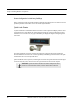

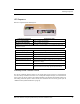

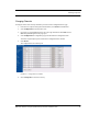

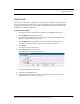
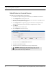
Table Of Contents
- Important Warnings
- Bio-Incompatibility Notice
- Compliance
- Introduction
- About this Guide
- Additional Detailed Documentation
- Contact Information
- Product Warranty
- Chapter 1
- Introduction
- Installation Checklist
- Installing Components
- Install the Central Server
- Install the Gateway
- Install Routers
- Place a Pendant into Survey Mode
- Determine Placement of Routers
- Quick Look Router
- Gateway/Router Reset Button
- LED Sequence
- Gateway/Router Channel Default
- Additional Gateway/Router Installation
- Changing Channels
- Router Depth
- Rebuild Subnet on Scanned Devices
- Scan Devices
- Chapter 2
- Introduction
- Transceiver Devices
- LED Light Indicator
- Installing Transceiver Devices
- Pull Cords/Emergency Call
- Check-in Pull Cord
- Pull Cord Transceiver with Extended Battery Pack
- Wall Mount Emergency Call
- Universal Transceiver
- Tamper
- Nurse Call
- Door/Window Transceiver
- Door/Window Transceiver with Reset Button
- PIR Sensor
- Smoke Detector
- Pendant Transceivers
- Activate the Battery
- Set up the Pendant
- Reset the Pendant
- Verify the Pendant Appears in the System
- Replace the Battery
- Test the System Operation
- Chapter 3
- Introduction
- Device Failure
- Router Failure
- Gateway Failure
- Chapter 4
- Specifications
- Power Cable Run Lengths
- Mesh Network Router/Gateway
- Quick Look Display for Quick Look Router
- Pendant Transceiver
- Pull Cord
- Nurse Call
- Door/Window Transceiver
- PIR Sensor
- Smoke Detector
- Universal Transceiver

Chapter 1: Installing Hardware Components
10 9600 Series Wireless Call System (0510-1078-D) - Hardware Installation Guide
Router Configuration in Multi-story Buildings
When a configuring a multi-story facility the Routers should be placed directly above one another as much as
possible to provide accurate location even in non-location required facilities.
Quick Look Router
A Quick Look Router is an 9600 Series Router connected to a wireless Quick Look Display. When an alarm
is sent from the Server to the Router, the wireless display shows the type of alarm, location data and alarm
information. As new alarms occur, they appear immediately; the display then begins scrolling through each
active alarm.
The Quick Look Router also acts as an integral part of the back-up reflector. This reflector functionally
allows the 9600 Series network to take over the responsibility of distributing alarm information to the Quick
Look Routers in the event of an inoperable Server.
Quick Look Routers can be supervised; a routine signal is sent from each Quick Look Router and if the signal
is not received by the system, a Device Fault event is generated in the Event List at the computer.
WA R N I N G: Quick Look Routers should not be added to multiple units. Since
Routers are used to determine location, inaccurate location data could result.