
User Manual

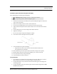

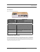


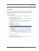
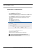
Table Of Contents
- Important Warnings
- Bio-Incompatibility Notice
- Compliance
- Introduction
- About this Guide
- Additional Detailed Documentation
- Contact Information
- Product Warranty
- Chapter 1
- Introduction
- Installation Checklist
- Installing Components
- Install the Central Server
- Install the Gateway
- Install Routers
- Place a Pendant into Survey Mode
- Determine Placement of Routers
- Quick Look Router
- Gateway/Router Reset Button
- LED Sequence
- Gateway/Router Channel Default
- Additional Gateway/Router Installation
- Changing Channels
- Router Depth
- Rebuild Subnet on Scanned Devices
- Scan Devices
- Chapter 2
- Introduction
- Transceiver Devices
- LED Light Indicator
- Installing Transceiver Devices
- Pull Cords/Emergency Call
- Check-in Pull Cord
- Pull Cord Transceiver with Extended Battery Pack
- Wall Mount Emergency Call
- Universal Transceiver
- Tamper
- Nurse Call
- Door/Window Transceiver
- Door/Window Transceiver with Reset Button
- PIR Sensor
- Smoke Detector
- Pendant Transceivers
- Activate the Battery
- Set up the Pendant
- Reset the Pendant
- Verify the Pendant Appears in the System
- Replace the Battery
- Test the System Operation
- Chapter 3
- Introduction
- Device Failure
- Router Failure
- Gateway Failure
- Chapter 4
- Specifications
- Power Cable Run Lengths
- Mesh Network Router/Gateway
- Quick Look Display for Quick Look Router
- Pendant Transceiver
- Pull Cord
- Nurse Call
- Door/Window Transceiver
- PIR Sensor
- Smoke Detector
- Universal Transceiver

9600 Series Wireless Call System (0510-1078-D) - Hardware Installation Guide 9
Installing Components
Determine Placement of Routers
Routers are powered by a plug-in power supply or central power supply. A backup battery is also included in
the Router enclosure. Factors that affect the placement of Routers are the availability of a power source and
sufficient coverage for the supervision of transceivers.
1. The first Router's location is in the proximity of the Gateway as specified on the floor plan. Using a
Pendant that is in Survey Mode, walk a distance from the Gateway until the light on the Pendant
starts blinking red. This indicates that the Router is out of range of the Gateway.
2. Walk back into range.
3. Mount Router within range of the Gateway and near a 110 VAC wall outlet or at the termination
point from the central power supply. Repeat steps 1 and 2 to mount subsequent Routers.
N
OTE: If using a 9V power supply, wiring from the power supply can be routed inside the wall or
(if preferred) mount the raceway for containing and concealing the wires leading from the
underside of the Router down to the 110 VAC wall outlet.
4. Placement of the Router should not be located over a stud and should be at a distance of one foot
from the bottom of the enclosure to the ceiling. The orientation of the Router should be vertical.
5. Using the rear plate of the Router as a template, place it level against the wall and mark the location
of the two mounting holes.
If the wiring from the wall outlet power supply or central power supply exits from being concealed
in the wall then locate the lower right corner of the rear plate (corner is cut out) over the exit hole.
6. Center punch each hole and drill in two nylon wall anchors (included). If the Router is located on a
concrete wall then you must use the wall anchors designed for use with concrete (not included).
7. Once the wiring has been run to the location of the Router attach the power supply wires to the
terminal block in the corner of the Router. If using a central power supply up to seven (7) Routers
may be daisy chained by terminating the next Router to the second terminal block. The minimum
field wire size to be employed shall be 22 AWG (0.36 mm
2
).
8. Ensure that the wires are pulled through the wire tie wrap, secure them tightly with the wire tie and
cut off excess.
9. Make certain that the Router’s ON/Off switch is in the ON position.
10. Place the rear plate of the Router into the recess on the back of the Router enclosure.
11. Place the Router over the wall anchors in alignment with the holes in the enclosure and insert two
screws (included). Verify Router is firmly secured to the wall to prevent device from falling.
12. If raceway is being used now is the time to apply it.
13. If the power is supplied by a wall outlet power supply then plug in the power supply.
14. If the power supply has a mounting tab, secure it to the outlet using the screw provided.
15. Repeat the above steps for the remaining Routers.
NOTE: A configuration map or floor plan of the facility is pre-determined with most 9600
Wireless Call Systems. Please rely on the configuration map or floor plan in conjunction
with the information provided below to determine Router placement.