
User Manual


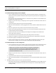

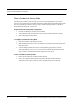
Table Of Contents
- Important Warnings
- Bio-Incompatibility Notice
- Compliance
- Introduction
- About this Guide
- Additional Detailed Documentation
- Contact Information
- Product Warranty
- Chapter 1
- Introduction
- Installation Checklist
- Installing Components
- Install the Central Server
- Install the Gateway
- Install Routers
- Place a Pendant into Survey Mode
- Determine Placement of Routers
- Quick Look Router
- Gateway/Router Reset Button
- LED Sequence
- Gateway/Router Channel Default
- Additional Gateway/Router Installation
- Changing Channels
- Router Depth
- Rebuild Subnet on Scanned Devices
- Scan Devices
- Chapter 2
- Introduction
- Transceiver Devices
- LED Light Indicator
- Installing Transceiver Devices
- Pull Cords/Emergency Call
- Check-in Pull Cord
- Pull Cord Transceiver with Extended Battery Pack
- Wall Mount Emergency Call
- Universal Transceiver
- Tamper
- Nurse Call
- Door/Window Transceiver
- Door/Window Transceiver with Reset Button
- PIR Sensor
- Smoke Detector
- Pendant Transceivers
- Activate the Battery
- Set up the Pendant
- Reset the Pendant
- Verify the Pendant Appears in the System
- Replace the Battery
- Test the System Operation
- Chapter 3
- Introduction
- Device Failure
- Router Failure
- Gateway Failure
- Chapter 4
- Specifications
- Power Cable Run Lengths
- Mesh Network Router/Gateway
- Quick Look Display for Quick Look Router
- Pendant Transceiver
- Pull Cord
- Nurse Call
- Door/Window Transceiver
- PIR Sensor
- Smoke Detector
- Universal Transceiver

9600 Series Wireless Call System (0510-1078-D) - Hardware Installation Guide 7
Installing Components
b. When using a single serial port server (PN 9600-0002) with cable (PN 0460-0124), connect the 9-
Pin connector from the Gateway to the single serial port server. Run Cat-5 wiring and terminate
each end with a RJ45 connector. Connect one end to the Ethernet connector on the bottom of the
single serial port server and the other end to the Ethernet switch.
Then, either plug the serial port into the CPS observing the polarity of the cable, red to (+ ) and
black to ( - ) or plug the power supply into a standard outlet. Using an uninterruptable power supply
(UPS) is recommended for standard output power.
6. Ensure that the wires are pulled through the wire tie wrap, secure them tightly with the wire tie and
cut off excess.
7. Place the rear plate of the Gateway into the recess on the back of the Gateway enclosure.
8. With the antenna pointing upwards, place the Gateway over the wall anchors in alignment with the
holes in the enclosure and insert two screws (included). Verify Gateway is firmly secured to the
wall to prevent device from falling.
9. Using the software loaded on the Central Server select the COM port assigned to the Gateway.
Refer to the section "Poll Server Settings" in the Series 6.0 Software Administrative Guide (PN
0510-1080).
To test the Gateway
1. Activate a transceiver and initiate an alarm event.
2. If the Gateway does not appear in the device list, verify that the appropriate communications port is
selected.
Install Routers
Routers receive signals from transceivers and re-transmit them to the Gateway. There are two
models of Routers, one with an internal antenna and one with an external antenna for greater
range. Routers can be supervised; a routine signal is sent from each Router and if the signal is
not received by the system, a Device Fault event is generated in the Event List at the computer.
The Router has four (4) single-color LED lights; two green and two red. For more information
on LED lights and LED sequence refer to “LED Sequence” on page 13.
The two lights furthest from the Reset Button indicate device transceiver communication
status These set of lights flashes briefly (once) every check-in (30 seconds by default), when a
tamper alarm is triggered or cleared, and when a data is forwarded.
• Green indicates communication is good and data is forwarded OK to the next Router.
• Red indicates communication failure and data is NOT forwarded to the next Router.
The two lights closest to the Reset Button indicate RS232 communication status. These set of lights flashes
briefly (once) when data is transmitted to an external RS232 device (i.e. Quick Look).
• Green indicates that the external RS232 device loopback is detected.
• Red indicates that the external RS232 device loopback is not detected.