
User Manual


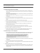

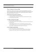
Table Of Contents
- Important Warnings
- Bio-Incompatibility Notice
- Compliance
- Introduction
- About this Guide
- Additional Detailed Documentation
- Contact Information
- Product Warranty
- Chapter 1
- Introduction
- Installation Checklist
- Installing Components
- Install the Central Server
- Install the Gateway
- Install Routers
- Place a Pendant into Survey Mode
- Determine Placement of Routers
- Quick Look Router
- Gateway/Router Reset Button
- LED Sequence
- Gateway/Router Channel Default
- Additional Gateway/Router Installation
- Changing Channels
- Router Depth
- Rebuild Subnet on Scanned Devices
- Scan Devices
- Chapter 2
- Introduction
- Transceiver Devices
- LED Light Indicator
- Installing Transceiver Devices
- Pull Cords/Emergency Call
- Check-in Pull Cord
- Pull Cord Transceiver with Extended Battery Pack
- Wall Mount Emergency Call
- Universal Transceiver
- Tamper
- Nurse Call
- Door/Window Transceiver
- Door/Window Transceiver with Reset Button
- PIR Sensor
- Smoke Detector
- Pendant Transceivers
- Activate the Battery
- Set up the Pendant
- Reset the Pendant
- Verify the Pendant Appears in the System
- Replace the Battery
- Test the System Operation
- Chapter 3
- Introduction
- Device Failure
- Router Failure
- Gateway Failure
- Chapter 4
- Specifications
- Power Cable Run Lengths
- Mesh Network Router/Gateway
- Quick Look Display for Quick Look Router
- Pendant Transceiver
- Pull Cord
- Nurse Call
- Door/Window Transceiver
- PIR Sensor
- Smoke Detector
- Universal Transceiver

Chapter 1: Installing Hardware Components
6 9600 Series Wireless Call System (0510-1078-D) - Hardware Installation Guide
To install the Gateway directly to Server computer
1. Locate a mounting site for the Gateway that is within a 12-foot reach of the Central Server. To minimize noise
interference, the Gateway should be a minimum of 10-feet away from any wireless device or any high powered
electrical device.
Placement of the Gateway should not be located over a stud. The Gateway should be at a one-foot distance from
the bottom of the enclosure to the ceiling.
2. Using the rear plate of the Gateway as a template, place it level against the wall and mark the location of the two
mounting holes.
3. Center punch each hole and insert two nylon wall anchors (included).
4. Make certain that the RS232/Power Cable is plugged into the Gateway and that the ON/Off switch is in the ON
position.
5. Place the rear plate of the Gateway into the recess on the back of the Gateway enclosure.
6. With the antenna pointing upwards, place the Gateway over the wall anchors in alignment with the holes in the
enclosure and insert two screws (included).
7. If preferred, mount the raceway for containing and concealing the wires leading from the underside of the
Gateway down to the Central Server.
8. Connect the 9-Pin serial connector from the Gateway to the serial port on the Central Server.
9. Plug the power supply into a standard outlet. Using an uninterruptable power supply (UPS) is recommended.
10. If the power supply has a mounting tab, secure it to the outlet.
11. Using the software loaded on the Central Server, select the COM port assigned to the Gateway. Refer to the
section "Poll Server Settings" in the Series 6.0 Software Administrative Guide (PN 0510-1080).
To install the Gateway in or near a wiring closet
1. Locate a mounting site for the Gateway within the wiring closet. Placement of the Gateway should not be located
over a stud. The Gateway should be at a one-foot distance from the bottom of the enclosure to the ceiling.
2. Using the rear plate of the Gateway as a template, place it level against the wall and mark the location of the two
mounting holes.
3. Center punch each hole and insert two nylon wall anchors (included).
4. Make certain that the RS232/Power Cable is plugged into the Gateway and that the ON/OFF switch is in the ON
position.
5. Depending on which serial port server you use, do one of the following:
a. When using a 4-port serial port server (PN 9450-0910) with cable (PN 0460-0101), connect the RJ45 connector
from the Gateway to the top side of the serial port server. The serial port server is located within the black box
mounting assembly.
NOTE: In some circumstances where RF performance is impaired by a shielded wiring
closets or the location of the covered area is at a significant distance from the wiring
closet, the Gateway can be located outside the wiring closet by making use of the
provided 50 foot RS232/Power Cable.