
User Manual
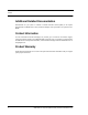


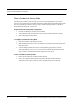
Table Of Contents
- Important Warnings
- Bio-Incompatibility Notice
- Compliance
- Introduction
- About this Guide
- Additional Detailed Documentation
- Contact Information
- Product Warranty
- Chapter 1
- Introduction
- Installation Checklist
- Installing Components
- Install the Central Server
- Install the Gateway
- Install Routers
- Place a Pendant into Survey Mode
- Determine Placement of Routers
- Quick Look Router
- Gateway/Router Reset Button
- LED Sequence
- Gateway/Router Channel Default
- Additional Gateway/Router Installation
- Changing Channels
- Router Depth
- Rebuild Subnet on Scanned Devices
- Scan Devices
- Chapter 2
- Introduction
- Transceiver Devices
- LED Light Indicator
- Installing Transceiver Devices
- Pull Cords/Emergency Call
- Check-in Pull Cord
- Pull Cord Transceiver with Extended Battery Pack
- Wall Mount Emergency Call
- Universal Transceiver
- Tamper
- Nurse Call
- Door/Window Transceiver
- Door/Window Transceiver with Reset Button
- PIR Sensor
- Smoke Detector
- Pendant Transceivers
- Activate the Battery
- Set up the Pendant
- Reset the Pendant
- Verify the Pendant Appears in the System
- Replace the Battery
- Test the System Operation
- Chapter 3
- Introduction
- Device Failure
- Router Failure
- Gateway Failure
- Chapter 4
- Specifications
- Power Cable Run Lengths
- Mesh Network Router/Gateway
- Quick Look Display for Quick Look Router
- Pendant Transceiver
- Pull Cord
- Nurse Call
- Door/Window Transceiver
- PIR Sensor
- Smoke Detector
- Universal Transceiver

9600 Series Wireless Call System (0510-1078-D) - Hardware Installation Guide 5
Installing Components
Install the Gateway
The Gateway receives signals from Routers and transceiver devices and sends them to
the Central Server. The Gateway can be supervised; if no information is received by the
system from the Gateway for a specified amount of time, a Device Fault alarm is
generated in the Event List at the computer.
The Gateway has four (4) single-color LED lights; two green and two red. For more
information on LED lights and LED sequence refer to “LED Sequence” on page 13.
The two set of lights furthest from the Reset Button indicate transceiver device communication status. These
set of lights flashes briefly (once) every check-in (15 seconds by default) and when data is received or
transmitted.
• Green indicates communication is good (received data is formatted properly or the transmitted data was
sent successfully).
• Red indicates communication failure (received data has an error or the transmitted data was NOT sent
successfully).
The two set of lights closest to the Reset Button indicate RS232 communication status with the Central
Server. These set of flights flashes briefly (once) when data is transmitted via an external RS232 device to the
Central Server.
• Green indicates communication is good (transmission data acknowledged by the Central Server).
• Red indicates communication failure (transmission data NOT acknowledged by the Central Server). A
repeating, dim red LED flash (flashes once per second) indicates the device operating normally. Refer to “LED
Sequence” on page 13
.
NOTE: The RF lights do not flash on the Router or Gateway in response to end device activity.
NOTE: The Gateway must be mounted at the maximum height from the ground and situated
where reception to affiliated Routers is not impaired.
Reset Button
Communication
Serial
Fail–Good
RF
Fail–Good
Reset Button