
User Manual
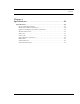

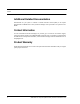
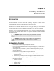


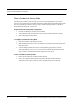
Table Of Contents
- Important Warnings
- Bio-Incompatibility Notice
- Compliance
- Introduction
- About this Guide
- Additional Detailed Documentation
- Contact Information
- Product Warranty
- Chapter 1
- Introduction
- Installation Checklist
- Installing Components
- Install the Central Server
- Install the Gateway
- Install Routers
- Place a Pendant into Survey Mode
- Determine Placement of Routers
- Quick Look Router
- Gateway/Router Reset Button
- LED Sequence
- Gateway/Router Channel Default
- Additional Gateway/Router Installation
- Changing Channels
- Router Depth
- Rebuild Subnet on Scanned Devices
- Scan Devices
- Chapter 2
- Introduction
- Transceiver Devices
- LED Light Indicator
- Installing Transceiver Devices
- Pull Cords/Emergency Call
- Check-in Pull Cord
- Pull Cord Transceiver with Extended Battery Pack
- Wall Mount Emergency Call
- Universal Transceiver
- Tamper
- Nurse Call
- Door/Window Transceiver
- Door/Window Transceiver with Reset Button
- PIR Sensor
- Smoke Detector
- Pendant Transceivers
- Activate the Battery
- Set up the Pendant
- Reset the Pendant
- Verify the Pendant Appears in the System
- Replace the Battery
- Test the System Operation
- Chapter 3
- Introduction
- Device Failure
- Router Failure
- Gateway Failure
- Chapter 4
- Specifications
- Power Cable Run Lengths
- Mesh Network Router/Gateway
- Quick Look Display for Quick Look Router
- Pendant Transceiver
- Pull Cord
- Nurse Call
- Door/Window Transceiver
- PIR Sensor
- Smoke Detector
- Universal Transceiver

Chapter 1: Installing Hardware Components
4 9600 Series Wireless Call System (0510-1078-D) - Hardware Installation Guide
6. Install transceiver devices. Transceiver devices transmit and receive data.
• Mount all fixed devices (i.e. Pull-Cords, Smoke Detectors, Door/Window transceivers).
• Enter transceiver information into the software, refer to the Series 6.0 Software User
Guide (PN 0510-1079) and Series 6.0 Software Administrator Guide (PN 0510-
1080).
7. Using the software, define the options, or system-wide settings to be applied to your facility’s 9600
Series Wireless Call System.
8. Test the operation of the system.
• Test the software.
• Test the system for sufficient coverage.
• Test the operation of the Supervision function.
Installing Components
Install the Central Server
The first step in the installation of the hardware components is to set up the Central Server.
1. Check to see that you have all the required equipment for setting up the Central Server.
• 50 megabytes (MB) of free hard disk space
• RF Technologies configured computer
• Keyboard
• Mouse
• UPS (uninterruptable power supply)
• Printer (optional)
• Remote connection hardware (if applicable)
2. Set up all the components of the Central Server.
3. Plug the components into the back of the Central Server (keyboard, mouse, printer).
4. Power the Central Server using the provided cord with an uninterruptable power supply (UPS). The
UPS should be plugged into a backup generator outlet.
WA R N I N G: When installing the Central Server, proper placement/mounting of
the server is important. Adequate precautions must be taken to prevent the server
from falling, causing injury to persons. Cables must be routed in a way to prevent
tripping hazards.
Any rack mounted Central Server must be install in a controlled environment that
maintains temperature between 50°F and 95°F and humidity between 20% and
50%.