
User Manual


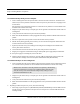

Table Of Contents
- Important Warnings
- Bio-Incompatibility Notice
- Compliance
- Introduction
- About this Guide
- Additional Detailed Documentation
- Contact Information
- Product Warranty
- Chapter 1
- Introduction
- Installation Checklist
- Installing Components
- Install the Central Server
- Install the Gateway
- Install Routers
- Place a Pendant into Survey Mode
- Determine Placement of Routers
- Quick Look Router
- Gateway/Router Reset Button
- LED Sequence
- Gateway/Router Channel Default
- Additional Gateway/Router Installation
- Changing Channels
- Router Depth
- Rebuild Subnet on Scanned Devices
- Scan Devices
- Chapter 2
- Introduction
- Transceiver Devices
- LED Light Indicator
- Installing Transceiver Devices
- Pull Cords/Emergency Call
- Check-in Pull Cord
- Pull Cord Transceiver with Extended Battery Pack
- Wall Mount Emergency Call
- Universal Transceiver
- Tamper
- Nurse Call
- Door/Window Transceiver
- Door/Window Transceiver with Reset Button
- PIR Sensor
- Smoke Detector
- Pendant Transceivers
- Activate the Battery
- Set up the Pendant
- Reset the Pendant
- Verify the Pendant Appears in the System
- Replace the Battery
- Test the System Operation
- Chapter 3
- Introduction
- Device Failure
- Router Failure
- Gateway Failure
- Chapter 4
- Specifications
- Power Cable Run Lengths
- Mesh Network Router/Gateway
- Quick Look Display for Quick Look Router
- Pendant Transceiver
- Pull Cord
- Nurse Call
- Door/Window Transceiver
- PIR Sensor
- Smoke Detector
- Universal Transceiver

9600 Series Wireless Call System (0510-1078-D) - Hardware Installation Guide 3
Chapter 1
Installing Hardware
Components
Introduction
The basic components of the system consist of the Central Server, the Gateway, the Router and the
transceiver devices. The Central Server is a RF Technologies configured computer that runs the software. It
contains the database and provides communication with the devices in the system.
Depending on your configuration, the system can include several Client computers. The Client computers
allow the user to perform such functions as admitting, discharging, and clearing alarms. Each Client
computer includes a touchscreen monitor that displays alarms as they occur on a floor plan of the facility.
This chapter provides detailed information about setting up the Central Server and installing hardware
components to use in conjunction with the software. It also provides an Installation Checklist to assist with
the installation process.
Installation Checklist
1. Read this guide in its entirety before proceeding with the installation.
2. Review the floor plan of the facility and make sure the equipment shipped to you matches what is
shown on the floor plan.
3. Walk through the facility and determine the physical location of all components of your system,
compared to the floor plan.
4. Determine how the Gateway(s) and Routers are going to be powered.
a. If the device is going to be powered by the CPS, refer to Figure 4.1 on page 49 to choose the
appropriate wire size.
b. If the device is powered using wall outlet power supply, an available outlet must be located
near the device (refer to Figure 4.2 on page 49 to choose the appropriate wire size).
5. Install System Components
• Install the Central Server
• If applicable in your facility, install the Client computer(s)
• Install the Gateway
• Install the Routers
WARNING: When installing product, you must follow standard
accepted safety practices such as wearing safety glasses.
WARNING: Before cutting openings or drilling holes through walls,
you must verify that you will not strike any wiring or plumbing.