
User's Manual
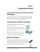
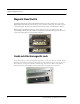

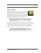
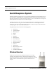
Table Of Contents
- Federal Communication Commission (FCC) Compliance
- Industry Canada Compliance
- Overview
- 9450 System
- Quick Response (QR) System
- Integrated Care Management (ICM) System
- Intended Audience
- Additional Detailed Documentation
- Contact Information
- Product Warranty
- Chapter 1
- Introduction
- Central Server and Client Computers
- Quick Look Display
- 9450 System
- Exit Alarm Controller
- Card Reader Access Device
- The Exit Alarm Zone
- Exit Alarm Receiver
- Magnetic Reed Switch
- CodeLock Electromagnetic Lock
- Alarming Band Receivers
- Alarming Band Zone
- Transmitters
- Wander Management Transmitter
- Alarming Band Transmitters
- Mother Transmitter
- Quick Response System
- Wireless Receiver
- Repeater
- Locator
- Paging Base
- Back-Up Interface
- Pendant Transmitters
- CodeWatch Transmitter
- Pull-Cords
- Check-in Pull Cord
- Smoke Detector
- PIR Sensor
- Door/Window
- Universal Transmitter
- Code Alert ICM System
- Gateway
- Router
- Transceivers
- Pull-Cords
- Nurse Call
- Door/Window Transceivers
- Smoke Detector
- PIR Sensor
- Universal Transceiver
- Pendant Transceivers
- Asset Transceiver
- Fall Management System
- Fall Management System Control Unit
- Fall Management System Sensor Pad
- Advanced 3-Way Care Solution
- Advanced 3-Way Control Unit
- Advanced 3-Way Care Sensor Pads
- Motion Sensor Pad
- Incontinence Sensor Pad
- Messaging Services
- Event Messaging
- Messaging Delays, Retries and Escalation
- Walkie-Talkie System
- Chapter 2
- Introduction
- Start the Software
- Window Conventions
- Touchscreen Monitor
- Quick Reference Tutorial
- Map Orientation
- Ruleset for Displaying Patient Name
- The Main Window
- The Menu Bar
- Monitor
- Tools
- Messaging
- Asset
- Help
- Top Toolbar
- Bottom Toolbar
- Low Battery Icon
- Chapter 3
- Introduction
- Commonly Used Terms
- Login and Passwords
- Units
- Device Supervision
- Global Lockdown
- Common Operations
- Admit
- Admit Information Windows
- Patient Admit Information Window
- Asset Admit Information Window
- Admit Information Tabs
- Patient Main Information Tab
- Discharge
- Escort
- Transfer
- Adjust
- Reports
- Silence

Chapter 1: Equipment Overview
6 Series 6.0 Software (0510-1065-A) - User Guide
9450 System
There are many transmitters and devices that can be used with the software. The transmitters and devices in this
section are supported by the 9450 System running the Series 6.0 Software application.
The 9450 System consist of the following equipment.
• Central Server and Client Computer(s)
• Quick Look Display(s)
• Exit Alarm Controller
• Exit Alarm Receiver
• Magnetic Reed Switch
• CodeLock Electromagnetic Lock
• Alarming Band Receivers
• Quick Look Display
• Transmitters
• Alarming Band
• Wander Management
• Mother
Exit Alarm Controller
The Exit Alarm Controller receives data from the Exit Alarm Receivers and issues an alarm if a transmitter is
detected in the Exit Alarm Zone, and the door is open. The Exit Alarm Controller contains a keypad, and/or card
reader access device, that allows authorized staff to reset the system after an alarm. The Exit Alarm Controller is
the device that triggers the alarm process for the Central Server and Staff Alert. For more information about the
Exit Alarm Controller, see the Delayed Egress Exit Alarm Controller Installation Guide.
Power: The red light indicates that
power is available to the system.
Signal: The yellow light indicates
that a signal has been received from
the Exit Alarm Receivers.
Status: The green light indicates
that the system is in bypass or that
the unit is disarmed.