Point-of-Use Drinking Water System OWNERS MANUAL E N V I R O N M E N TA L INC Ensuring the Safety of Your Water
Point-of-Use Drinking Water System OWNERS MANUAL Congratulations on the purchase of your new Sterilight Point-of-Use Drinking Water System. This unit is designed to operate for years with minimal maintenance. If you have any questions regarding the operation of the unit, these instructions, or how to obtain service on the unit, please contact your local Sterilight dealer, or contact Sterilight at www.r-can.com. This symbol is used throughout this manual to notify you of particularly important information.
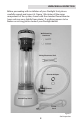
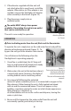
UNPACKING & INSPECTION Before proceeding with installation of your Sterilight Unit, please carefully unpack and inspect it. Figure 1 illustrates all the major components of the system, shown with the standard faucet diverter (your unit may vary slightly from photo). If anything appears to be broken or missing, please contact your Sterilight dealer.
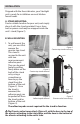
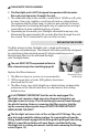
INSTALLATION Shipped with the faucet diverter, your Sterilight unit is ready for installation on most kitchen faucet heads. A. STAND MOUNTING: Find a suitable location for your unit, and simply place it with the stand provided. Excess hose and/or power cord may be wrapped inside the unit’s stand (Figure 2). B. WALL MOUNTING 1. To wall mount the unit, you must first Figure 2 remove the Counter-top stand mounting counter-top stand.
2. Locate a solid mounting surface (such as a wall stud). Attach the mounting hardware (Figure 7) and the unit (Figure 8). The Sterilight unit generates ozone from surrounding air. Locate the unit in an area where the air is breathable and free from dust or fumes. The unit MUST be mounted vertically, with the filter at the TOP of the unit. Figure 6 Separating stand from unit Figure 8 Hanging unit on Wall Mounting Pins Figure 7 Mounting Pin Installation C. CONNECTING TO THE FAUCET 1.
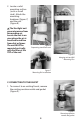
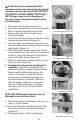
2. If the diverter supplied with the unit will not attach directly to your faucet, install the adapter. When done, or if the adapter is not needed, connect the Sterilight unit diverter valve assembly to the faucet (Figure 10). 3. Plug the power supply into an available outlet. The outlet MUST always have power available. Do not plug the unit into an outlet that can be switched on or off. Figure 10 Attaching diverter to Faucet The unit is now ready for operation.
PLEASE NOTE THE FOLLOWING 1. The Sterilight unit is NOT designed to operate with hot water. Run only cool tap water through the unit. 2. The ultraviolet lamp in the unit has a useful life of 10,000 on-off cycles or more. One cycle could be a small cup of water or a large pitcher. To maximize the life of the lamp, it is best to get a pitcher to store in the refrigerator for drinking during the day, as opposed to running it several times to draw individual glasses of water. 3.
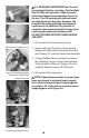
For the filter to be removed, the filter element must be saturated with water and all internal seals must be wet. DO NOT ATTEMPT TO REMOVE A FILTER ELEMENT THAT IS NOT WET. Doing so may result in breakage of the glass sleeve or lamp, and could result in personal injury. 1. Disconnect unit from power source. 2. Run water through the unit to insure that the filter is saturated and all seals are wet. 3. Remove the unit from its wall mount (if wall mounted) 4.
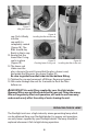
Figure 17 Wet glass sleeve Figure 18 Installing the filter into the cap cap. Push it firmly into the cap until it is completely seated (Figure 18). The filter should stay firmly in the to cap. 12. Ensure that the lower filter O-ring Figure 20 seal is in place Figure 19 Checking lower O-ring seal Installing the filter in the unit (Figure 19). 13. The lower seal slides over the glass sleeve in the unit. Ensure that the glass sleeve is wet, and guide the filter over the sleeve (Figure 20).
Figure 21—Draining the Unit Figure 22 Removing cover retaining screws It is EXTREMELY IMPORTANT that the unit be unplugged before servicing. The Sterilight Point-of-use unit contains a high intensity ultraviolet lamp that can damage tissues in the eye. The UV wavelengths cannot travel through the plastic housing. However, the lamp will be exposed during removal and replacement. In addition, it is possible to encounter hazardous electrical energy when removing the protective bottom cover.
Figure 26 (Internal Power Supply) Removing lamp 5. Loosen the lamp retention screw (External Power supply units–Figure 26). 6. Slide the lamp out carefully (Figures 26 and 27). 7. Insert the new lamp in the sleeve and reinstall the lamp. 8. Reinstall lamp wiring and the bottom cover. 9. Reinstall the filter as provided in the filter replacement instructions (see page 7). 10. Reconnect power. The unit is now ready for operation.
REPLACEABLE PARTS LIST Your Sterilight Point-of-Use treatment system has very few user-serviceable parts: Filter Cartridge................... SWM-C1 Filter Cap O-ring................ OR-SWM Lamp Assembly................. SWM-RL Quartz Sleeve..................... QS-SWM PARTS & SERVICE: Contact your Sterilight dealer. SWM SPECIFICATIONS Power requirements: SWM1, 115V AC, 20 WATTS SWM1/2, 220V AC, 20 WATTS Flow rate: Up to 2 lpm (0.5 gpm) Minimum inlet pressure: 30 PSIG Maximum operating pressure: 6.