
Installation Sheet

5of6
2018 QuoizelInc.
visit us on-line at www.quoizel.com
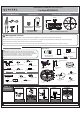
STEP 6
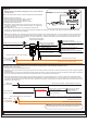
Making the wire connections without the received, the fan and light will be controlled by wall switches only.
a. Making the Wire Connections,
1. Remove the current-limiting from the receiver.
2. Wrap bare or green ground wire around green ground screw on the crossbar, no less than 2 inches from the end of the wire. Tighten the green
ground screw.
3. Use standard wire connectors (not included) to make all wire connections. Twist connectors until wires are tightly joined together. Wrap each
connection with approved electrical tape and carefully stuff all the connected wires into outlet box.
Note: If the electrical wire is going to be cut shorter than provided you will need to identify the "L" line wire and the "N" neutral wire before
you cut the excess wire off. One is labeled N and the other labeled L. To do this separate the "L" line wire and the "N" neutral wire as far as
you need to. Re-label the wire near where you want to make the cut. Be sure to mark the wire on the side of the fixture and not on the excess
wire being cut and removed.
Note: Refer to Step 8 for remote control transmitter bracket installation.
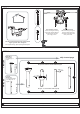
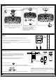
A. Making the Wire Connections
1. Connect fixture wires with label “Light L” together;
2. Connect fixture wires with label “N” together;
3. Connect fixture wires with label “ Motor L” togther.
Making the Wire Connections
1. Wrap bare or green ground wire around green ground screw on the
crossbar, no less than 2 inches from the end of the wire. Tighten the
green ground screw.
2. Use standard wire connectors (not included) to make all wire
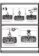
Making the wire connections using the receiver, for use with the
remote control
B.
O
N
ON
O
N
ON
D
I
P
DIP
1
2
3 4
connections. Twist connectors until wires are tightly joined together. Wrap each connection with approved electrical tape and carefully
stuff all the connected wires into outlet box.
: If the electrical wire is going to be cut shorter than provided you will need to identify the "L" line wire and the "N" neutral wire before
you cut the excess wire off. One is labeled N and the other labeled L. To do this separate the "L" line wire and the "N" neutral wire as far
as you need to. Re-label the wire near where you want to make the cut. Be sure to mark the wire on the side of the fixture and not on the
excess wire being cut and removed.
Note
Blue
identified with the Label “LIGHT L”
wire from fixture
White wire from fixture
identified with the Label “N”
Black wire from fixture
identified with the Label “MOTOR L”
AC L
AC N
White wire from outlet box
Black wire from outlet box (or Red)
Ground wire from Fixture
Bare, or Green
Ground wire
from outlet box
Green Ground Screw on the Crossbar
Ground wire from Hanger Frame
ON
ON DIP
1234
Black
with the Label “MOTOR L”
Wire from controller
White controller
with the Label “N”
Wire from
White urrent-limiting
with the Label “N”
Wire from c
Black current-limiting
with the Label “LIGHT L”
Wire from
Blue
with the Label “MOTOR L”
Wire from controller
Red Wire
White wire
from outlet box
Black wire from
outlet box (or Red)
Ground wire from Fixture
Bare, or Green
Ground wire
from outlet box
Green Ground Screw on the Crossbar
Ground wire from Hanger Frame
Red wire from
current-limiting
Current-limiting
Black current-limiting
with the Label “LIGHT L”
Wire from
White urrent-limiting with the Label “N”Wire from c
Blue
identified with the
Label “LIGHT L”
wire from fixture
Black wire from fixture identified with the Label “MOTOR L”
White wire from fixture identified with the Label “N”
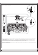
Warning: If you would like to use wall switch to control the light
and fan, please refer to the switch installation instructions.