
Installation Sheet

For Style RDE1716AWN
Installation Guide #IS-RDE1716AWN
1of2
Warnings and Cautions
Turn off electricity at circuit breaker or main fuse box before installation. Consult a licensed electrician if in doubt.
These instructions are provided for your safety. It is very important you read them completely before installing the fixture. We strongly
recommend that a licensed, professional electrician perform the installation.
Disconnect fixture from power source before replacing bulbs. Make sure bulbs are given sufficient time to cool before removal.
Pleasegoto forproductcleaningtips.Gotothe selection.
(4)A19MediumBase100WMaximum,bulbnotincluded.
MinimumHangingHeightis12”,MaximumHangingHeightis46.25”.
30-45minutes
Identifyandinspectallpartsbeforebeginninginstallation.Checkpackagecontentlistanddiagramsbelowtoensureallpartsare
present.Ifanypartsaremissingordamaged,donotattempttoassemble,install,oroperatethefixture.MissingParts?Contactyouroriginalplaceof
purchase.
www.quoizel.com Care+Maintenance
LightSource:
FixtureHangingHeight:
EstimatedAssembly Time:
Preparation:
Tools Required: Flathead screwdriver, Phillips screwdriver, pliers, wire cutters, wire strippers, electrical tape, safety glasses.
Note:This CONVERTIBLEfixturecanbemountedaspendantlightorsemi-flushlight.Refertorespective
installationsteps forinstallations.
2018 QuoizelInc.
visit us on-line at www.quoizel.com
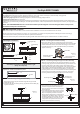
Package Contents
A
Crossbar Assembly
x1
Fixture Body
x1
D
Ceiling Canopy
x1
E
B
6” Rod
x2
C
12” Rod
x2
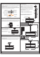
STEP 2A - Installing the Crossbar Assembly
A. Pass the supply wires from outlet box through the Crossbar
Assembly (A). Attach the Crossbar Assembly (A) to the Outlet Box
with the head of the Green Ground Screw facing you. Secure the
Crossbar Assembly (A) with Outlet Box Screws (not included).
Tighten until snug.
Supply Wires with
Ground Wire
Outlet Box Screws
(not included)
Outlet Box
A
Figure 2
STEP 3A Test Fitting Ceiling Canopy to Crossbar Assembly-
A.
eiling Canopy to the
ceiling
Remove mounting balls from the Crossbar Assembly (A). Fit the
C (D) Crossbar Assembly (A) and secure with
mounting balls. Note: The should be snug
against the and the mounting balls. If
Ceiling Canopy (D)
not, adjust the length
of the nipple on the Crossbar Assembly (A) by unscrewing the
preassembled hex nut and lock washer and then screwing the
mounting screws in or out of the crossbar until the correct length is
achieved. Once the Ceiling Canopy (D) is secure, remove the
mounting ball and Ceiling Canopy (D) and proceed to Step 4.
Mounting Screw
Hex Nut and
Lock Washer
Mounting Ball
A
D
Figure 3
ReleasedDate:2018-09-19
Swivel
x1
F
Assembly Instructions for Semi-flush Light
(Step 1A - Step 7A)
Part B and Part C will not be used in the assembly of the Semi-Flush
Light fixture. Please set aside these parts.
B
6” Rod
x2
C
12” Rod
x2
(Extra Parts include)
STEP 1A Install Ceiling Canopy to Fixture Body-
a. Pass supply wires and ground wire through the rod (G) and the
Ceiling Canopy (D).
c. Thread the rod (G), the Ceiling Canopy (D) and the Fixture Body (E)
together as shown.
D
E
Rod
x1
G
G
Figure 1
STEP 4A - Attach the Lanyard
A. The purpose of the lanyard is to provide a
means to support the fixture hands free
from the junction box while connecting the
electrical wires.
B.TurntheButtonStopsoitmaybeinserted
into a Crossbar slot. Make sure the Button
Stop is completely inside the Crossbar.
Slowly release the fixture to make sure it is
supported by the Button Stop. Proceed to
the wiring steps in the next step. Once you
are complete with the wiring, the Lanyard
will push into the junction box when the
fixture is placed for final mounting.
Button Stop
Lanyard
Slot
Figure 4