
Installation Sheet

STEP 3 Install Fixture Body-
A. Align Mounting Screws (B) to keyholes on the Fixture Body (D) and
twist the Fixture Body (D) until the Fixture Body (D) is hung safety.
B. By using Phillips screwdrivers, tighten Mounting Screws (B) from
keyholes on the Fixture Body (D) as needed to secure the Fixture
Body (D).
1of2
For Style QF5132C
Pleasegoto forproductcleaningtips.Gotothe selection.
LED31W
20-30minutes
Identifyandinspectallpartsbeforebeginninginstallation.Checkpackagecontentlistanddiagramsbelowtoensureallpartsare
present.Ifanypartsaremissingordamaged,donotattempttoassemble,install,oroperatethefixture.Contactyouroriginalplaceofpurchase.
www.quoizel.com Care+Maintenance
LightSource:
EstimatedAssemblyTime:
Preparation:
ToolsRequired:Flatheadscrewdriver, Phillips screwdriver,pliers,wirecutters,wirestrippers,electricaltape,safetyglasses.
Installation Guide #IS-QF5132C
2019 QuoizelInc.
ReleasedDate:2019-03-15
visit us on-line at www.quoizel.com
Warnings and Cautions
Turn off electricity at circuit breaker or main fuse box before installation. Consult a licensed electrician if in doubt.
These instructions are provided for your safety. It is very important you read them completely before installing the fixture. We strongly
recommend that a licensed, professional electrician perform the installation.
Package Contents
A
Crossbar
x1
C
Fixture Body
x1
B
Mounting
Screw
x2
D
Glass Shade
x1
E
Lock Screw
x3
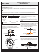
STEP 1 Install Crossbar-
A. Measure the distance between two keyholes on the top of the
Fixture Body (D). Use this distance to identify corresponding
mounting holes on the Crossbar (A) and thread Mounting Screws (B)
into mounting holes.
Figure 1
Outlet Box Screws
(not included)
A
Outlet Box
Green Ground
Screw
B
D
Keyhole
BOTTOM VIEW OF
FIXTURE BODY
BOTTOM VIEW OF
FIXTURE
BODY
(Step 1 Continued)
B. Attach slots on the Crossbar (A) to mounting holes on outlet box
with the head of green ground screw facing you. Secure the
Crossbar (A) with outlet box screws (not included). Tighten until
snug with screwdrivers
C. Test fit the Fixture Body (D) to Mounting Screws (B) and adjust
the length of Mounting Screws (B) so that the Fixture Body (D)
flush against the ceiling after installation. You may need to test fit
more than one time to achieve the correct length of the Mounting
Screw (B).
.
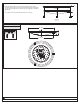
STEP 2 - Wire Connections
A. Wrap bare or green ground wire around green ground screw on the
crossbar, no less than 2 inches from the end of the wire. Tighten the
green ground screw.
B. Use standard wire connectors (not included) to make all wire
connections. Twist connectors until wires are tightly joined together.
Wrap each connection with approved electrical tape and carefully
stuff all the connected wires into the Outlet Box.
Green Ground Screw
on the Crossbar
White wire
from outlet box
White wire
from fixture
Black wire from
outlet box (or Red)
Black wire
from fixture
Bare, or Green
Ground wire
from outlet box
Ground wire
from Fixture
Figure 2
Figure 3
Phillips
Screwdriver
Keyhole
D
B
Outlet Box
3
0W
N
L
Ra>
9
0
2
5
W
-
3
5W
30
0
0K
5
0
0
0
K
27
0
0
K
40
0
0
K
E
T
L
40
0
1
2
5
6
Size:265*265*1. 2mm
A
C
3
0
R
S
2-
2
6
5
D
35W
A
C
1
20
V
R
a
>
8
0
N
S
J1
J1
J1
J2
J1
J1
J1
J2J2
J0
J1
J1
MOV
TVS
F1
+
-
BD1
C1
C2
C3
D1
D3
D4
D5
D6
Q1
Q2
R3
R4 R5
R6
R7
R8
R9
R10
R11
R12R13
R14 R15
R16
R17R18
R19R20
R21
R22
R23
R24 R25
R26
R27
R28
R29 R30
R31
R32
R33
U1
U2
U3
U4
U5
U6
X2
D8
D7
BD2
RL
1
J1-1
J1-2
J0
J1