
Installation Sheet
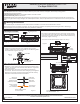

Package Contents
1of1
Assembly Instruction Sheet #IS-PCSD1713C
For Style PCSD1713C
Pleasegoto forproductcleaningtips.Gotothe selection.
Flatheadscrewdriver,Phillipsscrewdriver,pliers,wirecutters,wirestrippers,electricaltape,safetyglasses.
IntegratedLED16W
www.quoizel.com Care+Maintenance
ToolsRequired:
LightSource:
EstimatedAssemblyTime:
Preparation:
20-30minutes
Identifyandinspectallpartsbeforebeginninginstallation.Checkpackagecontentlistanddiagramsbelowtobesureallpartsare
present.Ifanypartsaremissingordamaged,donotattempttoassemble,install,oroperatethefixture.Contactcustomerserviceforreplacement
parts.
CompatibleDimmerSwitches:LutronDVELV-300PorLutronSELV-300P.
Warnings and Cautions
Turn off electricity at circuit breaker or main fuse box before installation. Consult a licensed electrician if in doubt.
These instructions are provided for your safety. It is very important you read them completely before installing the fixture. We strongly
recommend that a licensed, professional electrician perform the installation.
Crossbar
x1
Assembly
A
Mounting Screw
x2
B
G
ND
2.4mm
13 Ga13 Ga
C
Fixture Body
x1
STEP 1 Attach Crossbar Assembly to Outlet Box-
A. Attach the Crossbar Assembly (A) to Outlet Box and secure by
threading Outlet Box Screws (not supplied) into the Mounting Holes
on the Outlet Box. Tighten until snug.
Outlet Box
A
Outlet Box Screw
(not supplied)
Figure 1
STEP 3 - Attach Fixture Body to Crossbar
A. F .
Line up the holes on the side of the eiling anopy to the mounting
holes on the (A). Secure them with Mounting
Screws (B). Tighten until sung.
it excess cord and electrical wires in the ceiling canopy properly
cc
Crossbar Assembly
Your fixture is now assembled and ready to use. Enjoy!
A
B
Ceiling
Canopy
Figure 3
Thank you for purchasing a Quoizel product.
Need assistance with parts or assembly? Call Quoizel customer service at 1-800-645-3184
or visit us on-line at www.quoizel.com
2017 QuoizelInc.
ReleasedDate:2017-08-25
PCSD1713C
FINISH: POLISHED CHROME
G
ND
2.4mm
13 Ga13 Ga
NOTE: ALL DIMENSIONS ARE ROUNDED UP
TO THE NEAREST 1/4"
12.75” SQ.
10.5” SQ.
10.5” SQ.
4”
STEP 2 - Wire Connections
A. Wrap bare or green ground wire around green ground screw on the
crossbar, no less than 2 inches from the end of the wire. Tighten the
green ground screw.
B. Use standard wire connectors (not included) to make all wire
connections. Twist connectors until wires are tightly joined together.
Wrap each connection with approved electrical tape and carefully
stuff all the connected wires into the Outlet Box.
Figure 2
Green Ground Screw
on the Crossbar
White wire
from outlet box
White wire
from fixture
Black wire from
outlet box (or Red)
Black wire
from fixture
Bare, or Green
Ground wire
from outlet box
Ground wire
from Fixture