
Installation Sheet

Pleasegoto forproductcleaningtips.Gotothe selection.
Flatheadscrewdriver,Phillipsscrewdriver,pliers,wirecutters,wirestrippers,electricaltape,safetyglasses.
www.quoizel.com Care+Maintenance
ToolsRequired:
LightSource:
(4)ClearG9XenonBulbs40WMaximum(supplied)
EstimatedAssemblyTime:
Preparation:
20-30minutes
Identifyandinspectallpartsbeforebeginninginstallation.Checkpackagecontentlistanddiagramsbelowtobesureallpartsare
present.Ifanypartsaremissingordamaged,donotattempttoassemble,install,oroperatethefixture.Contactcustomerserviceforreplacement
parts.
Warnings and Cautions
1of2
Assembly Instruction Sheet #IS-PCPG1716C
For Style PCPG1716C
Turn off electricity at circuit breaker or main fuse box before installation. Consult a licensed electrician if in doubt.
These instructions are provided for your safety. It is very important you read them completely before installing the fixture. We strongly
recommend that a licensed, professional electrician perform the installation.
Disconnect fixture from power source before replacing bulbs. Make sure bulbs are given sufficient time to cool before removal.
Do not touch the bulb with bare hands use a cloth or glove.
2017 QuoizelInc.
ReleasedDate:2017-08-17
Thank you for purchasing a Quoizel product.
Need assistance with parts or assembly? Call Quoizel customer service at 1-800-645-3184
or visit us on-line at www.quoizel.com
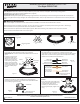
Package Contents
Crossbar
x1
A
C
Fixture Body
x1
Mounting Screw
x2
B
GND
Clear G9
Xenon Bulb
x4
E
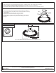
STEP 2 Install the Crossbar to the junction box-
.
A. Attach the Crossbar (A) to the Outlet Box with the head of the
Green Ground Screw facing you. Secure it with Outlet Box Screws
(not included), tighten until snug
Outlet Box
A
Outlet Box Screw
(not included)
Figure 2
Shade
x1
D
STEP 1 Install Bulbs and the Shade
IMPORTANT:
-
A. Insert bulbs (E) onto sockets and push snugly into place.
Do not touch the bulb with bare hands use a cloth or
glove.
C
E
D
Side Cable
Key
Holder
Button
Ring
Socket
B. Carefully insert sockets
with bulbs inside of the
Shade (D). Open the key
holder on the end of the
side cable by pushing the
button on the key holder.
Attach key holders on the
ends of side cables to the
ring of the Shade (D) as
shown.
Figure 1
STEP 3 - Making the Wire Connections
A. Use standard wire connectors (not included) to make all wire
connections. Twist connectors until wires are tightly joined together.
Wrap each connection with approved electrical tape and carefully
stuff all the connected wires into outlet box.
Figure 3
White Wire
from fixture
Black wire
from fixture
White wire
from outlet box
Black wire from
outlet box (or Red)
Bare, or Green
Ground wire
from outlet box
Ground wire
from fixture
Bare, or Green
Ground wire
from outlet box
OR
Ground wire
from fixture
Green Ground Screw
on the Crossbar
STEP 4 - Attach Fixture Body to
Crossbar
A. Line up the holes on the side of the
ceiling canopy and Fixture Body (C)
to the mounting holes on the
Crossbar (A). Secure them with
Mounting Screws (B). Tighten until
sung.
A
B
C
Figure 4