
Installation Sheet

2of3
2019 QuoizelInc.
ReleasedDate:2019-01-03
visit us on-line at www.quoizel.com
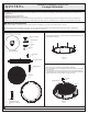
STEP 3 Install the Fixture Body to Support Rods-
A. Place the Fixture Body (G) onto Support Rods (H) and align holes
on the float plate to Support Rods (H). Secure the Fixture Body (G)
by using Lock Screws (F). Hand tighten until snug.
F
G
H
Figure 3
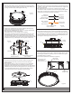
STEP 5 - Attach Lanyards
A. The purpose of the lanyard is to provide a means to support the
fixture hands free from the junction box while connecting the
electrical wires.
B. Turn the Button Stop so it may be inserted into a Inner Backplate
slot. Make sure the Button Stop is completely inside the Inner
Backplate. Slowly release the fixture to make sure it is supported by
the Button Stop. Proceed to the wiring steps in the next step. Once
you are complete with the wiring, the Lanyard will push into the
junction box when the fixture is placed for final mounting.
Lanyard
Button Stop
A
G
Figure 5
STEP 6 - Wire Connections
A. Wrap bare or green ground wire around green ground screw on the
crossbar, no less than 2 inches from the end of the wire. Tighten the
green ground screw.
B. Use standard wire connectors (not included) to make all wire
connections. Twist connectors until wires are tightly joined together.
Wrap each connection with approved electrical tape and carefully
stuff all the connected wires into the Outlet Box.
Figure 6
Green Ground Screw
on the Crossbar
White wire
from outlet box
White wire
from fixture
Black wire from
outlet box (or Red)
Black wire
from fixture
Bare, or Green
Ground wire
from outlet box
Ground wire
from Fixture
STEP 7 Install the Fixture Body to Inner Backplate-
A. Place the Fixture Body (G) onto the Inner Backplate (A) and align
side holes on the ceiling canopy to mounting holes on the side of the
Inner Backplate (A). By using screwdrivers, thread Mounting Screws
(B) into mounting holes on the side of the Inner Backplate (A) and
hand tighten until snug to secure the fixture.
Figure 7
A
B
Ceiling
Canopy
G
STEP 8 Install Crystals-
A. Place the Crystal (J) into the gap on the Fixture Body (G) first. And
then straight release the Crystal (J) until it is seated on the gap on
the Bottom Plate (H) properly.
B. Use the same process to install other Crystals (J).
1 2
J
J
Gaponthe
Fixture Body
Gaponthe
Bottom Plate
K
G
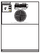
STEP 4 - Attach Inner Backplate to Outlet Box
A. Attach the Inner Backplate (A) onto the outlet box and make four
marks on the ceiling from a set of slot holes.
B. Remove the Inner Backplate (A). Using a 1/4” drill bit, drill holes at
each (4) locations marked on the ceiling.
C. Insert Wall Anchors (C) into drilled holes completely.
D. Pass supply wires and ground wire through the center hole of the
Inner Backplate (A). Attach the Inner Backplate (A) to outlet box.
Thread outlet box screws (not included) into mounting holes on the
outlet box. Pass Washers (E) over Screws (D) and thread Screws (D)
into Wall Anchors (C). Hand tighten until snug with screwdrivers.
Outlet Box
Supply Wires
with Ground Wire
Outlet Box Screws
(not included)
A
C
D
E
Figure 4
Slot Hole
Your fixture is now
assembled and
ready to use. Enjoy!
Figure 8