
Installation Sheet

Package Contents
Pleasegoto forproductcleaningtips.Gotothe selection.
Flatheadscrewdriver,Phillipsscrewdriver,pliers,wirecutters,wirestrippers,electricaltape,safetyglasses.
LED40W
www.quoizel.com Care+Maintenance
ToolsRequired:
LightSource:
EstimatedAssemblyTime:
Preparation:
20-30minutes
Identifyandinspectallpartsbeforebeginninginstallation.Checkpackagecontentlistanddiagramsbelowtobesureallpartsare
present.Ifanypartsaremissingordamaged,donotattempttoassemble,install,oroperatethefixture.Contactcustomerserviceforreplacement
parts.
Warnings and Cautions
1of2
Assembly Instruction Sheet #IS-PCDM1622C
For Style PCDM1622C
Turn off electricity at circuit breaker or main fuse box before installation. Consult a licensed electrician if in doubt.
These instructions are provided for your safety. It is very important you read them completely before installing the fixture. We strongly
recommend that a licensed, professional electrician perform the installation.
A
B
STEP 3 - Wire Connections
A. Wrap bare or green ground wire around green ground screw on the
crossbar, no less than 2 inches from the end of the wire. Tighten the
green ground screw.
B. Use standard wire connectors (not included) to make all wire
connections. Twist connectors until wires are tightly joined together.
Wrap each connection with approved electrical tape and carefully
stuff all the connected wires into the Outlet Box.
2018 QuoizelInc.
ReleasedDate:2018-03-13
Thank you for purchasing a Quoizel product.
Need assistance with parts or assembly? Call Quoizel customer service at 1-800-645-3184
or visit us on-line at www.quoizel.com
Fixture
Body
x1
Green Ground Screw
on the Crossbar
White wire
from outlet box
White wire
from fixture
Black wire from
outlet box (or Red)
Black wire
from fixture
Bare, or Green
Ground wire
from outlet box
Ground wire
from Fixture
F
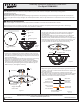
STEP 1 Attach Inner Backplate to Outlet Box-
A. Attach the Inner Backplate (A) onto the outlet box. Align one set of
holes on the Inner Backplate (A) to mounting holes on the outlet box
and make two marks on the ceiling from keyholes on the flat strap of
the Inner Backplate (A).
B. Remove the Inner Backplate (A) and drill proper holes on the ceiling
from marks. Insert Wall Anchors (C) into the holes properly.
C. Attach the Inner Backplate (A) to outlet box. Secure by threading
outlet box screws (not supplied) into mounting holes on the outlet
box and threading Self-tapping Screws (E) with Washers (D) into
Wall Anchors (C). Hand tighten until snug.
Figure 1
Figure 3
Inner Backplate
x1
Mounting Screw
x3
Wall Anchor
x3
Washer
x3
Self-tapping Screw
x3
C
D
E
G
N
D
Supply Wires and
Ground Wire
Outlet Box
A
C
E
D
Outlet Box Screw
(not supplied)
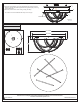
STEP 2 - Attach the Lanyard
A. The purpose of the lanyard is to provide a means to support the
fixture hands free from the junction box while connecting the
electrical wires.
B. Turn the Button Stop so it may be inserted into a inner backplate
slot. Make sure the Button Stop is completely inside the inner
backplate. Slowly release the fixture to make sure it is supported by
the Button Stop. Proceed to the wiring steps in the next step. Once
you are complete with the wiring, the Lanyard will push into the
junction box when the fixture is placed for final mounting.
Inner Backplate
Button Stop
Lanyard
Slot
Figure 2