
Installation Guide

2of2
Thank you for purchasing a Quoizel product.
Need assistance with parts or assembly? Call Quoizel customer service at 1-631-273-2700
or visit us on-line at www.quoizel.com
2015 QuoizelInc.
September2015
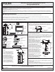
Chain (GG) alternating links. After
the wires are through the Fixture
Chain (GG), pull the Supply Wires
and the Ground Wire through the
Canopy Lock Ring (FF) and the
Ceiling Canopy (II) in order.
C. Attach one end of the Fixture Chain
(GG) to the Fixture Loop with one
Quick Link (HH). Lift the fixture and
Fixture Chain (GG) up and attach
the other end of the Fixture Chain
(GG) onto the Canopy Chain Loop
(EE) with another Quick Link (HH).
The fixture will now hang safely.
Close the chain loop at the Ceiling
Canopy Loop (EE).
D. Feed the Supply Wires and Ground
Wire through the Canopy Chain
Loop (EE) and Nipple (DD) into the
Outlet Box. Cut the wires leaving
Approximately 8” of wire extending
from the Outlet Box.
E. Refer to Step 5 for wire connections.
F. Raise the Ceiling Canopy (II) and
Canopy Lock Ring (FF) up the
Fixture Chain (GG) and over the
Canopy Chain Loop (EE). Tighten
the Canopy Lock Ring (FF) onto the
Canopy Chain Loop (EE) until tight.
Suggested chain length for Ceiling
height :
8’ ceiling : use 2 links of chain and 2
quick links
9’ ceiling : use 11 links of chain and 2
quick links
10’ ceiling : use 20 links of chain and
2 quick links
DD
GG
II
EE
FF
HH
HH
Supply
Wires and
Ground Wire
Figure 4
Figure 5
STEP 5 - Wire Connections
A. Use standard wire connectors (not included) to make all wire
connections. (Connectors are not included with fixture.) Twist
connectors until wires are tightly joined together. Wrap each
connection with approved electrical tape and carefully stuff all the
connected wires into outlet box.
Note: If the electrical wire is going to be cut shorter than provided
you will need to identify the "L" line wire and the "N" neutral wire
before you cut the excess wire off. One is labeled N and the other
labeled L. To do this separate the "L" line wire and the "N" neutral
wire as far as you need to. Re-label the wire near where you want to
make the cut. Be sure to mark the wire on the side of the fixture and
not on the excess wire being cut and removed.
White wire
from supply
Ribbed side of wire from fixture
identified with the Label “N”
Black wire from
supply (or Red)
Smooth side of wire from fixture
identified with the label “L”
Ground wire
from supply
Ground wire
from fixture
STEP 6 - Install Bulb
A. This fixture uses standard bulb
with medium base. Maximum 150
watts. Insert bulb and screw snugly
into place.
Your fixture is now assembled and
ready to use. Enjoy!
Figure 6
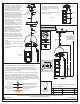
MLS1907IB
FINISH: IMPERIAL BRONZE
NOTE: ALL DIMENSIONS ARE ROUNDED
UP TO THE NEAREST 1/4"
PART NUMBER
1
NO.
PART NUMBER
REPLACEMENT PART
REQ.
M674CHIB
CHAIN
1
2
G12221PA
SHADE
4
Fixture
Loop
Bulb
Socket
(1) 150W
Bulb
(Not Supplied)
Medium
Base
4.5”Sq.
1”
123.5”
OVERALL HEIGHT
INCLUDES 96”
CHAINS AND
(2) QUICK LINKS
19.75”
16.25”
7.25”Sq.
2
1